+1 on the FZ-1 fuzeblock. I used one on my Concours to run the gps, extra lights, powered top box, etc. The switched and always-on option (by just moving the fuse) is great!martinh said:I am planning to wire up the lights to my FZ-1 fuze block. It is nice and small with the relay built into it.
Outstanding Group Buy! Solstice lights!
- Thread starter motocephalic
- Start date
Combo
DSN
Founding Member
2011 Site Supporter
2012 Site Supporter
2013 Site Supporter
2014 Site Supporter
I would have liked to have gone with another fuse block, lights and switch like others listed, but went cheaper and I think they will work just fine for my needs.
Fuse block:
http://www.easternbeaver.com/Main/Products/Fuseboxes/3_Circuit/3_circuit.html
Fog/running lights:
http://cgi.ebay.com/ebaymotors/Motorcycle-LED-Fog-light-enduro-cruiser-touring-yamaha-/250779329250?pt=Motorcycles_Parts_Accessories&hash=item3a639ce2e2
PB Switch:
http://cgi.ebay.com/ebaymotors/ws/eBayISAPI.dll?ViewItem&item=140403744770
I am out less than $100.00 for lights, fuse system and switch. I have tested the Lights and switch ----work just fine.
Japako brought up something that I've been thinking about for a while now. The Super Tenere headlights don't have a regular highbeam with a separate element in the bulb. They are, presumably, single element bulbs sine the highbeam is actually just the eyelid rolling backward/upward to let more light out and raise the light cut-off line. So the headlight wiring is going to be a bit different. I haven't looked at the service manual that I have (which technically is for the non-U.S. bike anyway), but presumably, there is only one power source going to the headlight since the bulbs are always on the same setting. There won't be two elements to power on and off, so the high-low beam switch is simply sending a signal to the mechanism that rolls the eyelid back.
If one is going to have aux. lights that only come on with the high beam switch and not low beam, or 100% at high beam and wired for a pwm for low beam, then wiring axillary lights into this setup is going to require a different setup than most other bikes. I agree that using a relay is going to be the best (and probably only) way to do this since the relay wiring will tap into the wire that signals the stock bike's eyelid and the light power source will need to come from elsewhere (fuseblock or direct from battery).
If one wants the aux. lights on all the time and at one power level, it will be as easy as any other bike since you can either tap into the headlight power wire for power or tap into the headlight power of any "ignition-hot" wire for the signal for an aux. light relay (the best way).
Something to think about when deciding how you are going to setup the lights.
Got my lights yesterday! Now what do I mount them to...hmmm? Maybe I'll set them up on my DL for the time being for a test run. I think I am going to mount these the same way, isolated from the headlights on their own system switched. I plan on running them low like I have in the past on other bikes. I have had no problems doing it that way for years. I may include it's own fusebox, something that I have never bothered to do. Giving me room of other trinkets. I have to find a nice bracket design. Maybe Altrider will see this and engage in a bracket of their own.
colorider
Moderator
Global Moderator
Founding Member
2011 Site Supporter
2012 Site Supporter
2013 Site Supporter
Good to hear you got them! Did you get the "prime" model?motocephalic said:Got my lights yesterday! Now what do I mount them to...hmmm? Maybe I'll set them up on my DL for the time being for a test run. I think I am going to mount these the same way, isolated from the headlights on their own system switched. I plan on running them low like I have in the past on other bikes. I have had no problems doing it that way for years. I may include it's own fusebox, something that I have never bothered to do. Giving me room of other trinkets. I have to find a nice bracket design. Maybe Altrider will see this and engage in a bracket of their own.
How are we doing on the group buy discount code?
I've been thinking about this more and I don't think there will be an easy way to hook up the solo prime to make them automatically dim on low beam and go 100% on highbeam because of the way the ST headlight is wired. Even if we use relays, it seems to me the following would be problematic; you would wire the pulse width modulator (pwm) between the lights and relay 1. Relay 1 would power on with the low beam. In this case, our light doesn't have a true lowbeam because of the eyelid. It has one element which is always on. So our choice is to activate the LED relay from the headlight wire or any other "ignition on" wire.
Now comes the tricky part. What do we do to make the LED go from 50% to 100%? If you have a relay2 activated by the wiring going to the eyelid (if that is even possible), then it could open relay2 and allow power to be sent to the LED (without an inline pwm) so the LED would give 100% power, however, then the LED would be getting power from two sources because relay1 would still be open. I don't know the effect of giving the LED power from two sources and/or if there would be other issues. Perhaps one of the dimmer switches (pwm), that Solstice is selling, could care for that. I don't know how they are wired, but it would seem that it still wouldn't work since any source we use for lowbeam would stay on and wouldn't be cut when we switch to highbeam. Anyone else determined a way this will work since our bikes act a bit different than most bikes that have separate low and high beam hot wires? Hoping that there is a way besides having to manually hit a button or turn a dial to go from 50% to 100% on the LED.
Now comes the tricky part. What do we do to make the LED go from 50% to 100%? If you have a relay2 activated by the wiring going to the eyelid (if that is even possible), then it could open relay2 and allow power to be sent to the LED (without an inline pwm) so the LED would give 100% power, however, then the LED would be getting power from two sources because relay1 would still be open. I don't know the effect of giving the LED power from two sources and/or if there would be other issues. Perhaps one of the dimmer switches (pwm), that Solstice is selling, could care for that. I don't know how they are wired, but it would seem that it still wouldn't work since any source we use for lowbeam would stay on and wouldn't be cut when we switch to highbeam. Anyone else determined a way this will work since our bikes act a bit different than most bikes that have separate low and high beam hot wires? Hoping that there is a way besides having to manually hit a button or turn a dial to go from 50% to 100% on the LED.
- Joined
- Feb 26, 2010
- Messages
- 2,126
I'm guessing a little bit here, but I imagine the 50/100% dimmer unit has:
12V in (power)
12V out (to LEDs)
12V in (50%/100% dim)
The second 12V input would be high or low indicating which dimming mode to use. It would be connected directly to the switch on the dimmer. The trick here would be tapping into the high beam switch signal and diverting it to the dimmer to signal the 50/100 switching. I don't think there is more than one "power" source for the dimmer, it gets all it needs from the 12V power in, and the PWM circuitry (a timer of sorts) is using the 12V input from the dimmer switch to signal whether it operates in steady-state or pulse (on-off-on) mode.
If we could see a schematic of the dimmer we could verify. Worst case I'm thinking you can create your own switched dimmer circuit if you knew what timing was required for the LEDs to operate at 50%.
Should work as long as the dimmer can handle the "lowbeam" inbound signal to remain on at all times. Then, when the second inbound signal comes in, the dimmer knows to start sending 100% non-modulated outbound power to the LED instead of the 50% modulated.
As long as the module's outbound power type (50% modulated or 100% non-modulated) isn't dependent on inbound signal1 turning off when inbound signal2 comes in, it should work. I imagine there are some motorcycles out there where the lowbeam remains on even once the highbeam comes on, correct? Ours will be a similar setup except the highbeam signal will be from the eyelid signal-wire instead of a highbeam element power wire. We'll still want (and probably need) to wire the low and highbeam signals with a relay so the actual power comes from another source then feeds the dimmer. Rather than the dimmer having one 12V inbound power source and two signal inbounds, I imagine it just has the two inbound power sources and sends modulated or non-modulated out to the LED depending on which inbound circuit is providing the power. That is why it will depend on if it is smart enough to change to non-modulated output when the "highbeam" power arrives and the "lowbeam" power remains on rather than shutting off.
As long as the module's outbound power type (50% modulated or 100% non-modulated) isn't dependent on inbound signal1 turning off when inbound signal2 comes in, it should work. I imagine there are some motorcycles out there where the lowbeam remains on even once the highbeam comes on, correct? Ours will be a similar setup except the highbeam signal will be from the eyelid signal-wire instead of a highbeam element power wire. We'll still want (and probably need) to wire the low and highbeam signals with a relay so the actual power comes from another source then feeds the dimmer. Rather than the dimmer having one 12V inbound power source and two signal inbounds, I imagine it just has the two inbound power sources and sends modulated or non-modulated out to the LED depending on which inbound circuit is providing the power. That is why it will depend on if it is smart enough to change to non-modulated output when the "highbeam" power arrives and the "lowbeam" power remains on rather than shutting off.
- Joined
- Feb 26, 2010
- Messages
- 2,126
The following diagram is for a PWM dimmer using a potentiometer (P1).
This I imagine would be the dimmer circuit for the knob style dimmer (the knob is basically P1).
To create a fixed 50/100 version of this you probably need two transitors - a P and an N type, or two Ns and an inverter wired in parallel, each outputting to a resistor of a predefined resistance to give the proper input voltage to the 555 timer (input 7 on the diagram) in order to achieve the proper timing (pulse width) for the desired brightness. The high beam signal would still be the input signal, and when it's off (low beam) the dimmer diverts the power through the 50% resistor. When the high beam is flipped on it diverts through the other resistor (only one transistor would be on at a time due to the inversion of signal on one of them) to achieve the 100% brightness.
This is all assuming that there is a constantly available 12V power source to power the lights. The whole design is ignorant of what the low beams are doing, as long as there is power supplied to the lights (either by ignition, battery via relay, etc). There is no switching being done via the low beam, it's all high beam driven.
Nice work. A 'highbeam signal only" setup seems like a clever way to do it.
I just got done sending an email to both the visionxsuperstore and VisionxUSA to see if we could get schematics for both of their dimmers and explained the way the super tenere eyelid works. We'll see what they say.
I just got done sending an email to both the visionxsuperstore and VisionxUSA to see if we could get schematics for both of their dimmers and explained the way the super tenere eyelid works. We'll see what they say.
- Joined
- Feb 26, 2010
- Messages
- 2,126
"Nice work" is actually working toward the end goal rather than "solutionizing." Nice work to you!Chadx said:Nice work. A 'highbeam signal only" setup seems like a clever way to do it.
I just got done sending an email to both the visionxsuperstore and VisionxUSA to see if we could get schematics for both of their dimmers and explained the way the super tenere eyelid works. We'll see what they say.
My gut tells me that the knob-style and the push button style are both resistor driven with no outside input signal, and will be no help with what we are trying to accomplish. I'm betting the dimmer circuit I've described above is what Twisted Throttle is probably trying to get built in a plug-n-play fashion so they can offer it as an option for their Denali kit (this is speculation, but based on fact nonetheless).
- Joined
- Feb 26, 2010
- Messages
- 2,126
I just realized after thinking about this some more that the above circuit is actually integrated INTO the Soltice Prime unit itself. I went and took another look at the product photos on the VisionX site and noticed that there is a little green wire sticking out of the new Soltice Primes that is not there on the Soltice Solos.Venture said:The following diagram is for a PWM dimmer using a potentiometer (P1).
This I imagine would be the dimmer circuit for the knob style dimmer (the knob is basically P1).

I believe that the green wire, if driven to an input voltage will control the output of the light. In this case, it seems obvious that having the green wire open signals full light output, driving it with an input voltage will cause the LED to modify it's pulse-width automatically.
This is really good news (assuming I got ANY of this correct - left my EE chops behind about 10 years ago) because it means that you could theoretically achieve the dimming function with a simple fixed resistor.
For example, the green wire:
1. Open=full LED output
2. Driven to 12V = no LED output
3. Driven to say 6V = 50% LED output (usually not linear, but you get the idea).
All you need to do is hook up the high beam switch so that when activated it channels the 12V through the proper resistor and voila, you get the % dim you are looking for. Easy peasy.
My new bet is that the dimmers that are sold through VisionX require 12V input and are nothing more than a potentiometer (dial knob) or two resistors on a switch (50/100 fixed).
I think you are onto something with that green wire and it likely has something to do with the "driver" that visionx mentioned before.
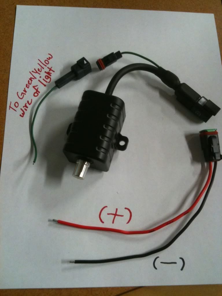
Visionxsuperstore replied. They don't have a schematic, but sent an image of both their dial dimmer and switched/fixed dimmer. I'm linking to the switch setup. Perhaps VisionX themselves will send a schematic since this retailer didn't have one.
Here is the image. Note where the green wire goes...to the green wire of the LED light(s). As Venture mentions and by looking at all the photos, it looks like the LED get powered from another source and this setup just sends a signal to the green wire. So it's still a mystery how the internals work, but it seems that whatever signal gets sent to the green wire is the key to it all.
This particular setup doesn't seem to allow for automatic dimming. In the end, perhaps it's not too big of a deal. One could run them at 50% most of the time, even when your brights are on, if you are riding where you'll have to be going between high and low beam a lot. If you are offroad or on a less trafficy road, then you can hit the switch and run them at 100% because it will be a long time between when you have to dim them. Probably satisfactory should an automatic solution get too complex or expensive.
- Joined
- Feb 26, 2010
- Messages
- 2,126
Yup, looks like I nailed it.
All we need is for VisionX or somebody with the dimmer to take a voltage reading of the green wire switched and non-switched. That will give the target input voltage that is needed for each case. I'm still pretty sure the 100% position is 0V and the other (50%) is what we really want to know. Once that is known we can start to think about how to get that voltage using the high beam switch.
All we need is for VisionX or somebody with the dimmer to take a voltage reading of the green wire switched and non-switched. That will give the target input voltage that is needed for each case. I'm still pretty sure the 100% position is 0V and the other (50%) is what we really want to know. Once that is known we can start to think about how to get that voltage using the high beam switch.
I sent it to you via email, did you get it?colorider said:Good to hear you got them! Did you get the "prime" model?
How are we doing on the group buy discount code?
I am curious, since i don't know that much about this stuff!!! Why can't I simply run a hot lead from battery, through a switch (along with Ground of course) and mount the lights and use them when I want? Why are there relays? What do they do?
I want to be able to turn off/on for both High and Low beams!!!
Oh, boy, I know I am asking for it now!!!!
>
I want to be able to turn off/on for both High and Low beams!!!
Oh, boy, I know I am asking for it now!!!!
>
beng a little simple, that is how I am setting mine up. The relay is included in the harness. The switch is also included. If I put in a fuse box, that will be extra.HoebSTer said:I am curious, since i don't know that much about this stuff!!! Why can't I simply run a hot lead from battery, through a switch (along with Ground of course) and mount the lights and use them when I want? Why are there relays? What do they do?
I want to be able to turn off/on for both High and Low beams!!!
Oh, boy, I know I am asking for it now!!!!
>
I know everything is included in the kit, but what about the mechanics of it? On the VSTrom site, people were adding an Eastern Beaver Relay kit to the OEM Headlights. Why? Does this reduce the voltage loaded onto the switch when we turn from low to high beams or something?
- Joined
- Feb 26, 2010
- Messages
- 2,126
The relay is there so that your switch and wires to/from it don't have to be beefed up to carry the electrical load required to run the lights. The relay allows the heavy wiring to be exactly where it needs it.HoebSTer said:I am curious, since i don't know that much about this stuff!!! Why can't I simply run a hot lead from battery, through a switch (along with Ground of course) and mount the lights and use them when I want? Why are there relays? What do they do?
I want to be able to turn off/on for both High and Low beams!!!
Oh, boy, I know I am asking for it now!!!!
>
Nothing about the position of the high/low beam switch would affect your ability to turn the lights off via the relayed switch.
colorider
Moderator
Global Moderator
Founding Member
2011 Site Supporter
2012 Site Supporter
2013 Site Supporter
Hmmm, no - but got your PM! Thanks!!!motocephalic said:I sent it to you via email, did you get it?
Rod