It doesn't look like you have the throttle side pushed on too far... When you applied the glue, which surface did you apply it to? Did you apply it to the inner sleeve of the grip, the throttle tube only, or both? I ask because if you put any glue on the inner sleeve of the grip, it will scrape off as you push the grip on, and can wind up on the inside of the throttle tube.
Oxford heated grips
- Thread starter RED CAT
- Start date
1tonn
New Member
I applied the glue to the throttle tube only. I thought I was careful not to push any glue out the end when I slid the grip into place. I am hoping to take the bike out for the first time tomorrow and maybe as I work the throttle it might free up. :-\
Millsy_666
New Member
I have a set of these grips installed they are within a millimeter or 2 of where yours are installed and i have no issues with throttle return, i would think as suggested glue has gotten somewhere it shouldn't
I too have the Oxford Adventures, and my throttle twists and snaps back just like when it was stock. I would be hesitant to ride it until I figured out what's making it stick.
1tonn
New Member
Thanks for the input. I took the bar end weight off and looked at the throttle tube and saw a small amount of glue on the edge giving just enough friction to keep it from closing. Cleaned it good and put the bar end weight, etc. back in place. Took my bike out for the first time this year and rode about 50mi. No issues at all, throttle snaps closed immediately. And also those heated grips are awesome. 47F. and they were very hot at 100%. Found 40% just right.1tonn said:Finally had a chance to install my new Oxford heated grips two days ago. To my dismay today when rotating the throttle open it doesn't want to return back to closed throttle on it's own. That don't seem right. I was SO careful with the glue and it went together without much fanfare. I've rotated the throttle several times and it seems that it wants to return on it's own but doesn't. The cables aren't binding either. So just wondering if anyone else has had a similar issue. Thanks
Scorpio
New Member
Oxford Heated Grips Install
I am sure that this has been discussed and sorry but wanted to get some ideas on the following:
Getting ready to install some Oxford Premium heated grips on the Tenere and looking for some tips. Since I have never installed grips before here are my questions:
I have already installed the electrical portion no problems
1. After cutting off the old grips suggestions on what to clean the bar with to remove the glue?
2. The grips came with glue but have read mix results on using this glue in that it dries to fast. Any other suggestions and do you also wire?
3. Any tips on installing the new grips? I know they must be correct as not to interfere with the other mechanism.
4. For those that have installed the controller on the Tenere the throttle side has the 2 bolts to install but don’t really like it there. The clutch side has one bolt and was wondering if this is sufficient to hold the controller.
Thanks
DJ
rfulcher
Active Member
Re: Oxford Heated Grips Install
I recently screwed up a set of grips using a special "grip glue" It was actually a gel type super glue and set up too quickly to position the grips. What I found worked best for me was 5 min epoxy. It gave me time to position the grips holds well.
I recently screwed up a set of grips using a special "grip glue" It was actually a gel type super glue and set up too quickly to position the grips. What I found worked best for me was 5 min epoxy. It gave me time to position the grips holds well.
Re: Oxford Heated Grips Install
::026:: for hairspray, works a treat ::008::
::026:: for hairspray, works a treat ::008::
Re: Oxford Heated Grips Install
I've installed these a few times on Teneres. First, throw the super glue in your junk drawer, and use it to glue broken coffee mugs. You don't want to fight with it when it sets up in about two seconds. Hairspray will work, as long as the initial fit it tight enough. The grips vary slightly in size as far as the inside dimension goes. I've had some go on VERY tight, where you can hardly get them on with no glue at all, and others will just practically fall on, and definitely need an epoxy to keep them from moving. I've always used Devcon two part epoxy. The grips have a rigid inner plastic sleeve, so I don't think safety wire will provide you any benefit like they do on soft grips.
You don't need a cleaner to get the factory glue off the bars and throttle tube. It rubs easily off with your finger, or a coarse textured rag.
I modified the little bracket, and made it fit under the single bolt on the clutch side. It's very secure there and I've never had an issue.
Rotate the throttle to it's stop, and check how the wiring will rotate with it. I don't know if you would ever need to apply the front brake lever while at full throttle, but still make sure it is positioned to where it won't interfere.
trasbeck
Member
Re: Oxford Heated Grips Install
Used hairspray, it finally let go after a season on there. Since I was away from home, I was offered a spray can of floor mat adhesive. Worked like a charm...gave plenty of time to position before drying..I left it overnight before riding. It did let go (softened) with grips on 100% but when cooled it was solid, so I didn't turn them up so high and no more problem. You should spend some time experimenting with where you want the wires to run before gluing them in place. For the control box, I cable tied it to the clutch master cylinder figuring to find a more solid attachment method. It's still there.
By the way, I think these are great heated grips, and a real value for the cost.
Scorpio
New Member
Re: Oxford Heated Grips Install
Thanks for the tips
Thanks for the tips
drive shaft
New Member
Re: Oxford Premium Adventure Heated Grips Install
frez said:Not wanting to pay the ridiculous price of the OEM heated grips I got a pair of Oxford Premium Adventure heated grips for the S10. These are exactly the same size as the S10s standard grips so do not need trimming.
First step was replacing the grips. The old grips were cut off with a Stanley knife. The bar ends remove very easily to allow the new grips to be slid on. They are a tight fit so I didn't bother with glue.
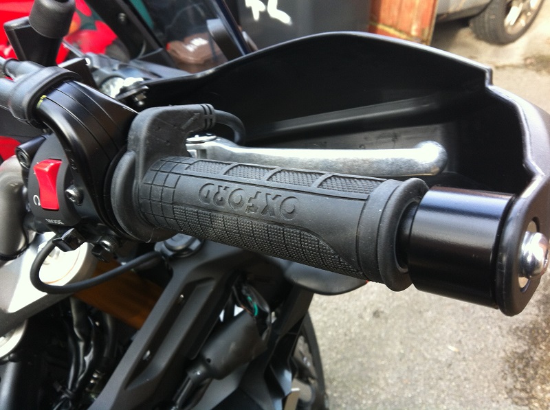
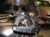
The left grip I had the wire coming out under the bar as shown here so it wouldnt get in the way of the passing light switch.
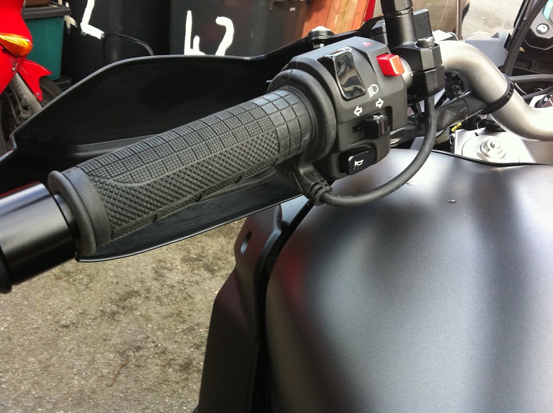
The right grip I had the wire go out over the top so it wouldn't get in the way of using the brake whatever the position of the throttle.
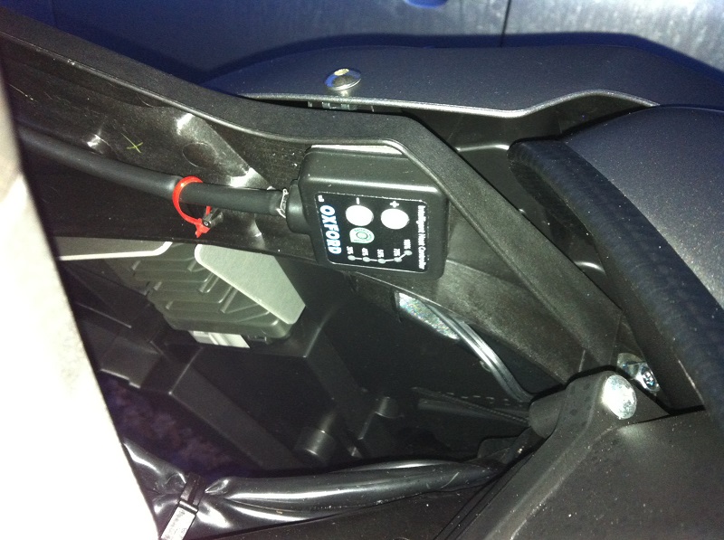
After much umming and ahhing and wanting to use muffs as well I decided to fit the controller on the inside of the right fairing just in front of the tank. I placed a cable tie through the back of the cable clip that was nearby in preparation so if the double sided tape failed on the controller it wouldn't fall far. On the subject of double sided tape, the piece that comes with the grips is thin and not ideal for this location which is not completely flat, I'd recommend using some different tape that was thicker and better suited for the purpose.
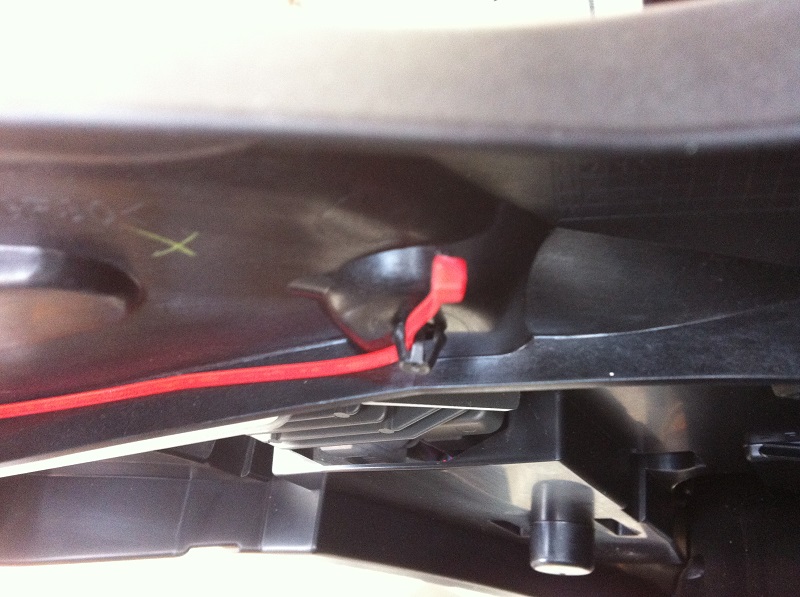
I trimmed back the sleeving to the controller to help with routing the cables, but then found that Oxford had cable joins under the sleeving so had to wrap it all up again in tape.
Controller fixed in place.
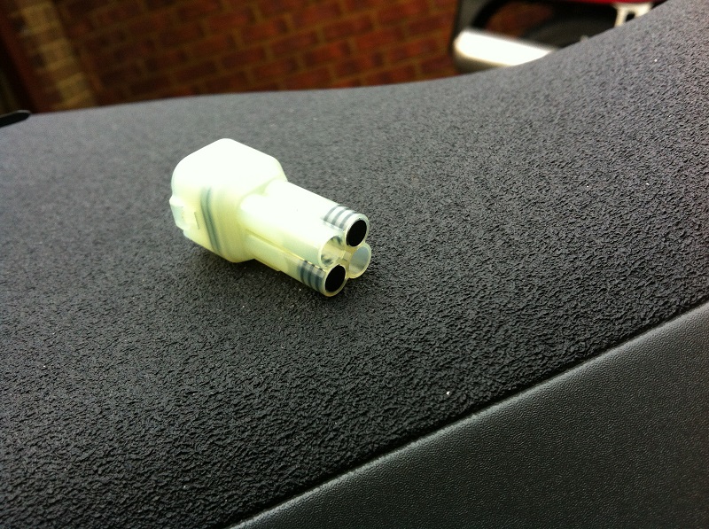
I had decided I was going to fit the Oxford grips to the OEM heated grip connector located behind the left fairing to the right of the battery. This connector already had a male fitting to the female socket, but without any pins.
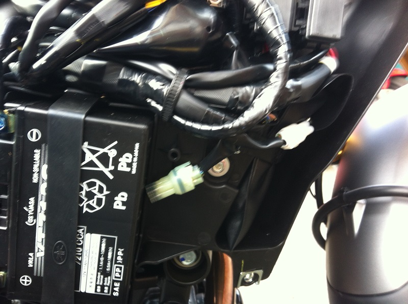
I removed two of the rubber plugs from the male side of the connector corresponding with the black wire (earth) and black/green wire (live when engine is running).
Each wire was then trimmed and connected to pins I had bought off ebay.
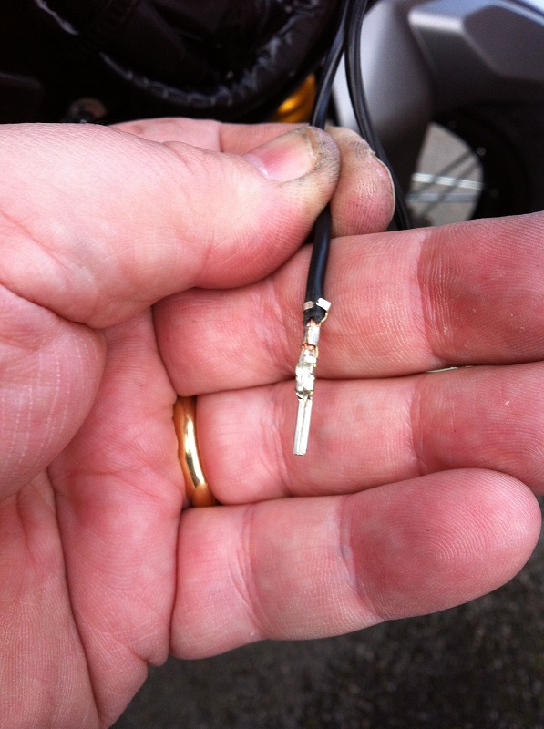
All very satisfactory in the end.
Here's a picture that better shows the location.
- Joined
- Jul 6, 2011
- Messages
- 35
Re: Oxford Premium Adventure Heated Grips Install
::026::
I have the exact set up on mine. Used it a bunch last winter and it worked great!
Only problem I've had is that the throttle side (very tight getting it on) loosened with heat and would gradually throttle off when hot.
I slid the throttle side off a few weeks ago and scuffed up the plastic throttle tube with a small screwdriver. A fair amount of super glue in there as well seems to be holding it in place.
SparrowHawkxx
Active Member
Re: Oxford Premium Adventure Heated Grips Install
Frez
Good write up on the installation.
I installed these same grips on my bike and positioned the grips about the same as you did; this is the best position for the routing of the cables. I did however, glue my grips with some high temp epoxy, JB Weld epoxy (600 degrees F).
I also used a different controller which is the purpose of this reply, to show another option for the controller.
A little background before I get into it.
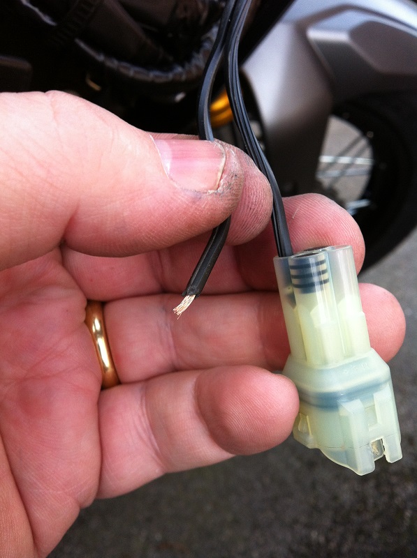
I bought a 2013 Tenere about 3 years ago and made the mistake of getting it with the OEM heated grips. The grips heated ok but the wire broke on the throttle side where it enters the grip (not easily repaired). This happened after only 2 years and 14,000 miles on the bike. I have seen where several others have had this same problem. I would be curious if this is also a problem on the 2014 and newer models.
About five years ago I mounted some Oxfords on my 2009 DL650 VStrom and I found this supplier, Lockitt (Lockitt.com), where they gave you the option of getting a Warm and Safe Heat Troller instead of the Oxford controller. I still have this bike and after 108,000 miles I have had no problems with the grips or controller.
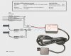
Use a Warm and Safe Heat Troller instead of the Oxford controller
The Heat Troller has a control module with a separate control knob at the end of a 5 foot cord so you can mount the control knob where it is easy to reach and mount the control module in an out of the way location.
I checked with Lockitt again and they were still selling the Oxfords with the option of the Warm and Safe Heat Troller.
They recommend going with the Heat Troller and one reason is that the knob is easier to use with winter gloves on.
I ordered this from Lockitt (Lockitt.com),
Oxford Premium Heaterz Adventure Heated Grips OF690Z - $89.95
With the dash mounted (Velcro) Heat Troller - an additional $45.00
If you already have the Oxford grips, the Heat Troller can be ordered separetely from www.warmnsafe.com/heat-trollers/ .
Supplies Used
Besides the JB Weld for the grips, other supplies I used in my installation was some heat shrink to go over soldered wire splices and some 1/4" and 3/8” Black Vinyl Sleeving. You could certainly do this installation without the sleeving but it helps to hide and protect the wiring and also looks much better.
I ordered several feet of the 1/4", 3/8”, and ½” sleeving to have on hand for other projects.
I ordered from kayjayco.com. On the kayjayco website, select “Cable Coverings” from the menu.
In the next screen, choose your covering in the drop down menu and select:
1/4" Black Vinyl 105 C Sleeving ($0.41 / foot)
3/8" Black Vinyl 105 C Sleeving ($0.64 / foot)
(edit) I see now that Cycle Terminal also has sleeving. See it listed on the main menu under Tubing.
Remove OEM heated grips and controller (2013 Super Tenere)
Replace with Oxford Premium Heaterz Adventure Heated Grips and Warm and Safe Heat Troller.
Reference Picture 1 below, for some people that is all you need and you can stop reading here.
For others that want to see more detail, read on. I have included the excruciating details on placement of the control module, control knob and cable routing detail. See Installation of the The Heat Troller below.
The OEM heated grips and controller were removed. The male connector attached to the OEM grips and controller would be reused so the four wires were cut about 5” from the connector. These four wires are described below.
Note that only two of the four wires are used to connect to the Heat Troller which supplies the power to the Oxford grips.
The two unused wires were cut a little shorter and at different lengths to prevent them from contacting each other.
But what if this is just a new installation and not a replacement of the OEM heated grips?
If that is the case, I would do what Frez did. Go back to page 5, reply 73 and see his pictures 6, 7, 8, 9 and the associated descriptions.
The OEM heated grip connector comes with a male fitting already connected to the female socket, but without any pins.
The connector is a Sumitomo sealed HM 090 series 4 pin connector. You can just order the male pins. Crimp the wires to the pins and insert into the connector.
Some sources to order the pins are:
Cycle Terminal http://www.cycleterminal.com/hm-sealed-series-090.html
Eastern Beaver Sumitomo HM Sealed Series - http://easternbeaver.com/Main/Elec__Products/Connectors/Sealed/SM-HM/sm-hm.html
For reference these are the 4 wires in the OEM heated grips connector
Black/green - 12v off the headlight relay (12 V with engine running) -- Used as the 12 V source for Heat Troller and Oxford Grips
Black - ground -- Used for ground connection
Blue/black - 12v off the key switch (12 V with ignition on) -- Not used
Light Green/white - ECU trigger -- Not used
Installation of the The Heat Troller (control module and control knob)
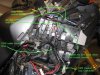
Remove both the lower and upper cowlings on the right side of the bike.
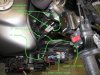
Picture 2 below shows where the control module is mounted and how the twisted red and black power wires are routed from the control module down to the OEM heated grips connector.
You can see:
A) The location of the Heat Troller control module and the zip ties that secure the module in place. You can also see where the hole was drilled under the plastic shelf for the zip ties to go through. The extra wiring from the control module is bundled together and placed on top of the control module.
B) The twisted red and black wires on the control module are routed down to the OEM heated grips connector and secured with the OEM cable bundle strap. Just above the connector you can see the plastic sleeving that was used to cover the wiring and connections, about 5” long.
Connecting the wires: Connecting the wires: Use about a 5” long piece of the 1/4" sleeving to slide over the twisted red and black wires and push it towards the control module. Slide some heat shrink up each wire, red and black. Connect/solder the red wire to the Black/green wire from the OEM heated grips connector and connect the black wire to the Black wire from the connector. Cover the connections with the heat shrink then slide the sleeving down towards the connector to cover the connections and also to retain the two unused wires (Blue/black and Light Green/white). In the picture you can see the blue in the Blue/black wire (unused) as it comes out of the connector and into the sleeving.
Picture 3 below shows how the control knob cable is routed with the twisted blue and white grip wires towards the heated grip connectors. The control knob cable continues on to the left side of the handlebar.
You can see:
A) The location of the Heat Troller control module.
B) The control knob cable coming from the control module.
C) The twisted blue and white wires that go from the control module up to the heated grip connectors. The Oxford heated grips come with the grip connectors and each connector has a short red and a black wire coming out the bottom side. This is where the twisted blue and white wires will be connected to.
Connecting the wires: Slide a piece of the 1/4" sleeving about an 8” long then a piece of the 3/8" sleeving about a 7” long over the twisted blue and white wires and push them towards the control module. Slide heat shrink over each of the two wires, blue and white.
Connect/solder the blue wire to both of the red wires.
Connect/solder the white wire to both black wires.
Cover both the connections with heat shrink.
Slide the 3/8" sleeving all the way up to the grip connectors covering the four wires and the connections.
Slide the smaller 1/4" sleeving up so that it overlaps the larger sleeving about an inch. This smaller sleeving will only be covering the twisted blue and white wires.
NOTE: The grips have no polarity and are wired in parallel so the wires could be soldered together in one of two ways; either as stated above [the blue wire to both red wires and the white wire to both black wires] or alternatively you could wire it this way [the blue wire to both black wires and the white wire to both red wires].
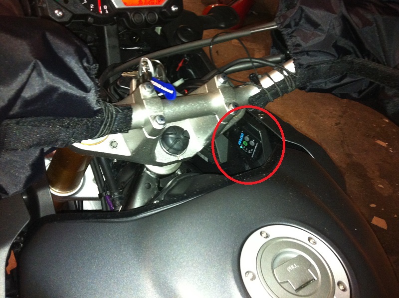
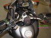
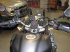
Picture 4 below shows where the control knob is mounted on the left side of the handlebar between the switch housing and the mirror bracket.
You can see:
A) The green dots follow the routing of the control knob cable. Notice that it goes underneath the hand guard bracket and is secured to the bracket with a black zip tie.
B) The purple dots follow the routing of the heated grip cables.
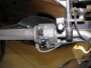
Picture 5 below shows the details of mounting the control knob
A) Route the control knob cable under the hand guard bracket.
The green dots follow the routing of the control knob cable.
B) Place the stick on Velcro (comes with the controller) on top of the handle bar and bottom side of the control knob housing.
C) Place the control knob housing on top of the handle bar and pull it back against the hand guard bracket. Pull the cable snug and secure it with a zip tie.
What helps to secure the control knob in place is that the back corner of the knob housing is up against the hand guard bracket on one side and against the switch housing on the other side. The Velcro does not hold much but does what it needs to do.
Picture 6 below shows some details on the left side.
You can see:
A) The control knob is mounted between the switch housing and the mirror bracket.
B) The Velcro strip under the control knob.
C) The left grip cable is tucked in out of the way under the switch housing.
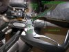
Picture 7 below shows some details on the right side.
You can see:
A) How the right grip is oriented.
B) The grip cable has no obstructions as it is rotated back.
Picture 8 below shows the overall layout:
Dec 2017 Edit - This procedure was edited do to some corrections, clean it up some, and to provide an update. Currently have 64,000 miles on bike (40,000 miles on the grips).
Update: This installation was done with 14000 miles on the bike. I had a failure in March 2017 with 47,000 miles on the bike (33K on the grips).
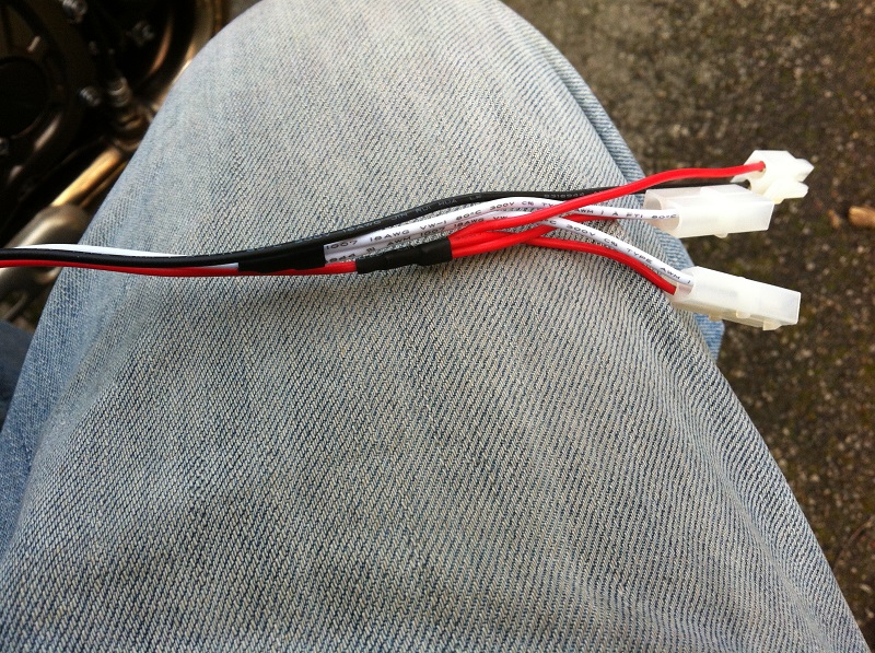
A wire broke just above the connector that goes to the left grip. See picture 3 below, the yellow tape marks the left grip connector, green tape marks the right grip connector. Steering back and forth was bending the wire sharply just above the connector and it eventually broke. I repaired the break then wrapped each wire between the connector and green/yellow tape with some 3M Temflex rubber tape to act as a strain relief. Also put a zip tie around the wires at the yellow/green tape to secure them to the wiring bundle behind them. This eliminated any sharp bends in the wiring when the steering was turned.
Other than that the grips have worked great and would not do anything else different if I were to do it again.
Frez
Good write up on the installation.
I installed these same grips on my bike and positioned the grips about the same as you did; this is the best position for the routing of the cables. I did however, glue my grips with some high temp epoxy, JB Weld epoxy (600 degrees F).
I also used a different controller which is the purpose of this reply, to show another option for the controller.
A little background before I get into it.
I bought a 2013 Tenere about 3 years ago and made the mistake of getting it with the OEM heated grips. The grips heated ok but the wire broke on the throttle side where it enters the grip (not easily repaired). This happened after only 2 years and 14,000 miles on the bike. I have seen where several others have had this same problem. I would be curious if this is also a problem on the 2014 and newer models.
About five years ago I mounted some Oxfords on my 2009 DL650 VStrom and I found this supplier, Lockitt (Lockitt.com), where they gave you the option of getting a Warm and Safe Heat Troller instead of the Oxford controller. I still have this bike and after 108,000 miles I have had no problems with the grips or controller.
Use a Warm and Safe Heat Troller instead of the Oxford controller
The Heat Troller has a control module with a separate control knob at the end of a 5 foot cord so you can mount the control knob where it is easy to reach and mount the control module in an out of the way location.
I checked with Lockitt again and they were still selling the Oxfords with the option of the Warm and Safe Heat Troller.
They recommend going with the Heat Troller and one reason is that the knob is easier to use with winter gloves on.
I ordered this from Lockitt (Lockitt.com),
Oxford Premium Heaterz Adventure Heated Grips OF690Z - $89.95
With the dash mounted (Velcro) Heat Troller - an additional $45.00
If you already have the Oxford grips, the Heat Troller can be ordered separetely from www.warmnsafe.com/heat-trollers/ .
Supplies Used
Besides the JB Weld for the grips, other supplies I used in my installation was some heat shrink to go over soldered wire splices and some 1/4" and 3/8” Black Vinyl Sleeving. You could certainly do this installation without the sleeving but it helps to hide and protect the wiring and also looks much better.
I ordered several feet of the 1/4", 3/8”, and ½” sleeving to have on hand for other projects.
I ordered from kayjayco.com. On the kayjayco website, select “Cable Coverings” from the menu.
In the next screen, choose your covering in the drop down menu and select:
1/4" Black Vinyl 105 C Sleeving ($0.41 / foot)
3/8" Black Vinyl 105 C Sleeving ($0.64 / foot)
(edit) I see now that Cycle Terminal also has sleeving. See it listed on the main menu under Tubing.
Remove OEM heated grips and controller (2013 Super Tenere)
Replace with Oxford Premium Heaterz Adventure Heated Grips and Warm and Safe Heat Troller.
Reference Picture 1 below, for some people that is all you need and you can stop reading here.
For others that want to see more detail, read on. I have included the excruciating details on placement of the control module, control knob and cable routing detail. See Installation of the The Heat Troller below.
The OEM heated grips and controller were removed. The male connector attached to the OEM grips and controller would be reused so the four wires were cut about 5” from the connector. These four wires are described below.
Note that only two of the four wires are used to connect to the Heat Troller which supplies the power to the Oxford grips.
The two unused wires were cut a little shorter and at different lengths to prevent them from contacting each other.
But what if this is just a new installation and not a replacement of the OEM heated grips?
If that is the case, I would do what Frez did. Go back to page 5, reply 73 and see his pictures 6, 7, 8, 9 and the associated descriptions.
The OEM heated grip connector comes with a male fitting already connected to the female socket, but without any pins.
The connector is a Sumitomo sealed HM 090 series 4 pin connector. You can just order the male pins. Crimp the wires to the pins and insert into the connector.
Some sources to order the pins are:
Cycle Terminal http://www.cycleterminal.com/hm-sealed-series-090.html
Eastern Beaver Sumitomo HM Sealed Series - http://easternbeaver.com/Main/Elec__Products/Connectors/Sealed/SM-HM/sm-hm.html
For reference these are the 4 wires in the OEM heated grips connector
Black/green - 12v off the headlight relay (12 V with engine running) -- Used as the 12 V source for Heat Troller and Oxford Grips
Black - ground -- Used for ground connection
Blue/black - 12v off the key switch (12 V with ignition on) -- Not used
Light Green/white - ECU trigger -- Not used
Installation of the The Heat Troller (control module and control knob)
Remove both the lower and upper cowlings on the right side of the bike.
Picture 2 below shows where the control module is mounted and how the twisted red and black power wires are routed from the control module down to the OEM heated grips connector.
You can see:
A) The location of the Heat Troller control module and the zip ties that secure the module in place. You can also see where the hole was drilled under the plastic shelf for the zip ties to go through. The extra wiring from the control module is bundled together and placed on top of the control module.
B) The twisted red and black wires on the control module are routed down to the OEM heated grips connector and secured with the OEM cable bundle strap. Just above the connector you can see the plastic sleeving that was used to cover the wiring and connections, about 5” long.
Connecting the wires: Connecting the wires: Use about a 5” long piece of the 1/4" sleeving to slide over the twisted red and black wires and push it towards the control module. Slide some heat shrink up each wire, red and black. Connect/solder the red wire to the Black/green wire from the OEM heated grips connector and connect the black wire to the Black wire from the connector. Cover the connections with the heat shrink then slide the sleeving down towards the connector to cover the connections and also to retain the two unused wires (Blue/black and Light Green/white). In the picture you can see the blue in the Blue/black wire (unused) as it comes out of the connector and into the sleeving.
Picture 3 below shows how the control knob cable is routed with the twisted blue and white grip wires towards the heated grip connectors. The control knob cable continues on to the left side of the handlebar.
You can see:
A) The location of the Heat Troller control module.
B) The control knob cable coming from the control module.
C) The twisted blue and white wires that go from the control module up to the heated grip connectors. The Oxford heated grips come with the grip connectors and each connector has a short red and a black wire coming out the bottom side. This is where the twisted blue and white wires will be connected to.
Connecting the wires: Slide a piece of the 1/4" sleeving about an 8” long then a piece of the 3/8" sleeving about a 7” long over the twisted blue and white wires and push them towards the control module. Slide heat shrink over each of the two wires, blue and white.
Connect/solder the blue wire to both of the red wires.
Connect/solder the white wire to both black wires.
Cover both the connections with heat shrink.
Slide the 3/8" sleeving all the way up to the grip connectors covering the four wires and the connections.
Slide the smaller 1/4" sleeving up so that it overlaps the larger sleeving about an inch. This smaller sleeving will only be covering the twisted blue and white wires.
NOTE: The grips have no polarity and are wired in parallel so the wires could be soldered together in one of two ways; either as stated above [the blue wire to both red wires and the white wire to both black wires] or alternatively you could wire it this way [the blue wire to both black wires and the white wire to both red wires].
Picture 4 below shows where the control knob is mounted on the left side of the handlebar between the switch housing and the mirror bracket.
You can see:
A) The green dots follow the routing of the control knob cable. Notice that it goes underneath the hand guard bracket and is secured to the bracket with a black zip tie.
B) The purple dots follow the routing of the heated grip cables.
Picture 5 below shows the details of mounting the control knob
A) Route the control knob cable under the hand guard bracket.
The green dots follow the routing of the control knob cable.
B) Place the stick on Velcro (comes with the controller) on top of the handle bar and bottom side of the control knob housing.
C) Place the control knob housing on top of the handle bar and pull it back against the hand guard bracket. Pull the cable snug and secure it with a zip tie.
What helps to secure the control knob in place is that the back corner of the knob housing is up against the hand guard bracket on one side and against the switch housing on the other side. The Velcro does not hold much but does what it needs to do.
Picture 6 below shows some details on the left side.
You can see:
A) The control knob is mounted between the switch housing and the mirror bracket.
B) The Velcro strip under the control knob.
C) The left grip cable is tucked in out of the way under the switch housing.
Picture 7 below shows some details on the right side.
You can see:
A) How the right grip is oriented.
B) The grip cable has no obstructions as it is rotated back.
Picture 8 below shows the overall layout:
Dec 2017 Edit - This procedure was edited do to some corrections, clean it up some, and to provide an update. Currently have 64,000 miles on bike (40,000 miles on the grips).
Update: This installation was done with 14000 miles on the bike. I had a failure in March 2017 with 47,000 miles on the bike (33K on the grips).
A wire broke just above the connector that goes to the left grip. See picture 3 below, the yellow tape marks the left grip connector, green tape marks the right grip connector. Steering back and forth was bending the wire sharply just above the connector and it eventually broke. I repaired the break then wrapped each wire between the connector and green/yellow tape with some 3M Temflex rubber tape to act as a strain relief. Also put a zip tie around the wires at the yellow/green tape to secure them to the wiring bundle behind them. This eliminated any sharp bends in the wiring when the steering was turned.
Other than that the grips have worked great and would not do anything else different if I were to do it again.
Attachments
-
 34.5 KB Views: 129
 -
 64.5 KB Views: 133
 -
 53.8 KB Views: 133
 -
 48.6 KB Views: 124
 -
 48 KB Views: 115
 -
 36.9 KB Views: 115
 -
 47.5 KB Views: 117
 -
 46.4 KB Views: 114
st art
New Member
Heated grips conector help needed.
So i installed Oxford heated grips on my 2012 S10.
I found ignition swiched wire in OEM conector and used that as a triger wire for a relay. I turn the key to on and i hear a relay click. All is good.
When i start the engine the power to the grips goes off. (?). Turn the bike off and turn the key on and grips work fine again. No blown fuses.
If anybody could give me a clue what to look for it would be great. THX.
Sent from my SM-G900W8 using Tapatalk
Re: Heated grips conector help needed.
your relay probably has two set of contacts, normally closed, and normally open.
A normally open set of contacts will close when the relay is energized, giving your wired device power.
A normally closed set of contacts will open when the relay is energized turning your wired device off.
You may be wired to the wrong set of contacts on the accessory relay.
st art
New Member
Re: Heated grips conector help needed.
Thanks anyway Buelligan.
Sent from my SM-G900W8 using Tapatalk
This relay has only 4 legs. So that can't be it.Buelligan said:your relay probably has two set of contacts, normally closed, and normally open.
A normally open set of contacts will close when the relay is energized, giving your wired device power.
A normally closed set of contacts will open when the relay is energized turning your wired device off.
You may be wired to the wrong set of contacts on the accessory relay.
Thanks anyway Buelligan.
Sent from my SM-G900W8 using Tapatalk