Heated Grip Plug

RMac

Member
Founding Member
Joined
Nov 24, 2010
Messages
392
Location
Phoenix AZ area
Kevhunts said:
Pictures?
Sorry, will not be able to post pics in the near future. I commute on a weekly basis as I live about 150km from my work so not at home to take pics just now. This weekend I am heading off on a business trip for ~1 week.

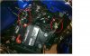
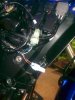
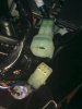
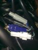
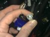
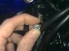
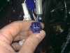
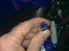
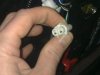
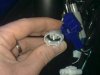
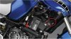
The connectors are easy to find and sit at the front of the battery/fuse box/wiring compartment on the RHS of the bike, about parallel with the top of the battery. Not easy to see from the photos on-line as they are neatly tucked in behind the wiring loom.
 

RMac

Member
Founding Member
Joined
Nov 24, 2010
Messages
392
Location
Phoenix AZ area
Got this pic from Yamaha's website. I have drawn a red circle around the region where the connectors are located. They are tucked in behind the wiring loom.
 

Attachments

SpeedStar

XT12 and DL650
Founding Member
2011 Site Supporter
2012 Site Supporter
2013 Site Supporter
Vendor
Joined
Sep 17, 2010
Messages
1,388
Location
San Diego, Ca
Thanks for the pic RMac! That will come in handy for us when the time comes.
 

RMac

Member
Founding Member
Joined
Nov 24, 2010
Messages
392
Location
Phoenix AZ area
SpeedStar said:
Thanks for the pic RMac! That will come in handy for us when the time comes.
I never thought about taking pics as I installed the grips. In retrospect that would have been good to do. I'll remember that next time ;)

Here are some overall impressions and comments on the OEM heated grips and the install...

OEM grips: Very nice piece of kit. The fit and look is great on the bike. The modified throttle cable housing very neatly routes the RHS grip cable and looks great. The location of the controller in front of the LH mirror is a matter of taste perhaps. I did not like the look of that location from pictures on-line so I ordered Wasp's heated grip controller bracket to mount under the instrument panel. However, I am not sure that I will use Wasp's bracket now because I kind of like the look of it in the intended Yamaha location when seen in person. Also easier to reach and adjust. Another thing is that Yamaha's bracket mounting to the controller unit includes rubber grommets that I assume are there to minimize vibration being transferred to the controller unit. Otherwise, why include them? I would recommed people to install the controller in the intended Yamaha location first to get a feel for the look and the ergonomics in person before spending money on other solutions. At maximum setting the grips seem to take about 5-10 minutes to fully heat up, but by that time are really nice and toasty.

Installation: It went reasonably smoothly given that I have never installed new grips before. The pictorial instructions with the kit are adequate. Removal of the old LH grip was easy enough when I used a long, slim kebab skewer to poke in between the rubber and handlebar to work and separate the glue and at the same time squirting a water and detergent solution into the gap to lubricate. The only thing that required effort was shoving the LHS grip onto the handlebar. I removed quite a bit of skin from the base of my thumb from friction when pushing the new grip on. Don't think it was such a good idea / necessary to use full strength A+B epoxy glue. It was hardening fast as I tried to shove the grip on. That thing is never coming off unless I hack it off! The routing of the heated grip cable in the new throttle cable housing also had me scratching my head for some time before I figured it out. The RHS of the handlebar needs to be drilled with a 4.5mm drill bit for the locator pin in the new throttle cable housing. There is a punch mark on the bars from the factory to show you where to drill - fool proof. I didn't have a 4.5mm metal drill bit and found that 4mm bit worked just fine if not better because it gave a nice and snug fitting to the throttle cable housing guide pin. Cable routing was straightforward. Yamaha provide the interface cable to go from the connector (discussed in this thread) to the various grip connectors.
 

colorider

Moderator
Global Moderator
Founding Member
2011 Site Supporter
2012 Site Supporter
2013 Site Supporter
Joined
Sep 25, 2010
Messages
5,442
Location
Sidney, NE
RMac said:
Got this pic from Yamaha's website. I have drawn a red circle around the region where the connectors are located. They are tucked in behind the wiring loom.
Thanks - that will be invaluable when the time comes!!!
 

markjenn

Active Member
Founding Member
Joined
Oct 22, 2010
Messages
2,427
Location
Bellingham, WA
I'll 2nd the request for someone to post a good picture of the actual heated grip connector on the bike. Would help immensely in sorting the correct connector for those of us wwant to do a plug-n-play loom for aftermarket heated grips. If something unusual, maybe we can source someplace to buy cheaper in quantity. Thanks!

- Mark
 

HoebSTer

New Member
Founding Member
2011 Site Supporter
2012 Site Supporter
Joined
Sep 29, 2010
Messages
2,883
Location
ISSAQUAH, WA USA
Jim from Eastern Beaver has asked me if anyone has a picture of the OEM connectors on either the bike or the end of the Yamaha heated grips. From there he can properly identify and get us what we need.

Thanks Guys. Oh this goes for the light connector at the same location on the bike that take the Yamaha accessory lights.
 

RMac

Member
Founding Member
Joined
Nov 24, 2010
Messages
392
Location
Phoenix AZ area
I managed to get back home, so here you go:

#1 Fullview.jpg, main heated grip connector (include with bike) to the front, OEM heated grip loom connectors to the rear (blue and white to the controller, grey and black to the grips)

#2 Grip and Spot.jpg, grip connector upper, spotlight connector lower

#3 Grip Connector.jpg, opened grip connector

#4 Spot female, protective cover remove on spotlight connector
 

Attachments

RMac

Member
Founding Member
Joined
Nov 24, 2010
Messages
392
Location
Phoenix AZ area
#5 Connectors to Grips, connector at other end of OEM grip kit wiring loom. Blue and white to the controller, grey and black to the heated grips

#6 Grey and black females to heated grips

#7 Grey and black males to the heated grips

#8 Blue connector male
 

Attachments

markjenn

Active Member
Founding Member
Joined
Oct 22, 2010
Messages
2,427
Location
Bellingham, WA
Wow, thanks for all the pictures. This is a lot more complicated than I thought as it appears the harness includes a lot of the point-to-point wiring for the controller and grip elements. On Suzukis, for example, there is just a connector with switched power and ground - all other wiring between the controller, grips, etc. is in the accessory.

- Mark
 

HoebSTer

New Member
Founding Member
2011 Site Supporter
2012 Site Supporter
Joined
Sep 29, 2010
Messages
2,883
Location
ISSAQUAH, WA USA
Eastern BEaver has returned my email after I have sent him the pics. Here are the two part numbers for the connectors we all will need in adding our own heated grips.

Sumitomo sealed 2P090wp-MT
Sumitomo unsealed 2P090-HM

He is great to work with and responds quickly. Remember, he lives in Japan, and ships easily to USA.
 

RMac

Member
Founding Member
Joined
Nov 24, 2010
Messages
392
Location
Phoenix AZ area
markjenn said:
Wow, thanks for all the pictures. This is a lot more complicated than I thought as it appears the harness includes a lot of the point-to-point wiring for the controller and grip elements. On Suzukis, for example, there is just a connector with switched power and ground - all other wiring between the controller, grips, etc. is in the accessory.

- Mark
Maybe I didn't make it so clear from the way I presented the pictures? The heated grip connector that is part of the original bike wiring harness is shown in picture #3 on pg2, lower 4-pin female connector. This is the connector people who want to add their own, non-OEM, heated grips need to worry about.

The rest is for information as there was a request for details about the other connectors. As shown in picture #1, the wiring loom provided with the OEM heated grip kit traverses over the top of the battery to the rear of the electrical compartment. The wiring loom provided with the OEM heated grip kit has the corresponding 4-pin male connector on one end that connects to the 4-pin female on the bike's harness, upper connector shown in picture #3; and four connectors at the other end, the grey and black connectors that supply the grips and the white and blue connectors that go to the grip controller, as shown in picture #5.

Hoebster, I am not familiar with heated grip kits and how they are typically wired, but unless cutting and splicing is done the first connector in any non-OEM harness will need to be the 4-pole male, upper connector in picture #3. This is a four pole connector so 4P should appear in the name.
 

colorider

Moderator
Global Moderator
Founding Member
2011 Site Supporter
2012 Site Supporter
2013 Site Supporter
Joined
Sep 25, 2010
Messages
5,442
Location
Sidney, NE
RMac said:
unless cutting and splicing is done the first connector in any non-OEM harness will need to be the 4-pole male, upper connector in picture #3. This is a four pole connector so 4P should appear in the name.
This appears to be the only one we will need to be involved with. I'll have to look and see if I still have any 4-pin male connectors (and contacts) left from when I wired my ST1300. I sourced all my needs (including the crimping tool) from Electrical Connection, referenced in an earlier post of mine.
 

markjenn

Active Member
Founding Member
Joined
Oct 22, 2010
Messages
2,427
Location
Bellingham, WA
Sorry I'm being dense, but why are their four pins in the heated grip connector rather than two?

- Mark
 

Koinz

Active Member
Founding Member
2011 Site Supporter
2012 Site Supporter
2013 Site Supporter
2014 Site Supporter
Joined
Nov 13, 2010
Messages
2,100
Location
Newtown, PA
Coud it be +.- for each side? Not sure if there's a relay involved either.
 
B

Bundu

Guest
I recently installed my grip heaters and fog lights on my S10 (OEM stuff)
I noticed that the grip heaters were only ON once the engine was running, but the fog lights came on as soon as the ignition was turned ON - I didn't like the fogs being on whilst ign ON and engine not running, so I rewired the fogs relay 12V to the wire that feeds the grips relay - My main reason for this was that I always ride with the fogs ON, as I ride a lot in town and they increase my visibility substantially and I also have an alarm on the bike, so I can't move it without turning the ignition on and didn't want the fogs to hammer my battery every time I set off, or be ON whilst starting the bike.

On the question about the wires going to the grip plug (coming from S10):
Blue/black=12V when ignition is ON
Black/green=12V when engine is running (fed Fog relay from here)
Black=Ground
Green/White=goes to ECU

All works well!
 

colorider

Moderator
Global Moderator
Founding Member
2011 Site Supporter
2012 Site Supporter
2013 Site Supporter
Joined
Sep 25, 2010
Messages
5,442
Location
Sidney, NE
Bundu said:
On the question about the wires going to the grip plug (coming from S10):
Blue/black=12V when ignition is ON
Black/green=12V when engine is running (fed Fog relay from here)
Black=Ground
Green/White=goes to ECU
This is GOOD info that will come in very handy for wiring non-OEM grips, etc!!!

Thanks!!!
 

rocca

New Member
Founding Member
2011 Site Supporter
Joined
Oct 19, 2010
Messages
44
Location
UK
Hi Bundu

Any comments on the fogs? Quality gear would you say?

Those and the crash bars are the only Yamaha accessories I haven't (yet) put on my bike.

To echo what RMac says about the OEM heated grips, I've just had them fitted and am impressed with the performance and neatness of the installation (no external rotating wire on the throttle grip, which should also aid longevity).
 
Top