rfulcher
Active Member
I installed a Rostra Electronic cruise control on my 2013 over the holidays. I haven’t seen a posting on this recently. I have installed 4 or 5 Audiovox vacuum operated cruise controls in the past and this was still challenging. The Rostra was actually simpler once the connections were located and verified. Thanks to Gary AKA SuperCruise on AdvRider forum. It took a couple of days with most of the time absorbed with problem solving, thinking things through, and double checking my work. I probably spent a couple of hours just thinking about and checking the linkage to the throttle bell crank and servo placement. I would not have thought that the servo would fit under the seat without the thread by justbob on this forum. I could probably install a Rostra unit in a day now.
Working on this sure makes the 2014 Super Tenere with OEM cruise look good.
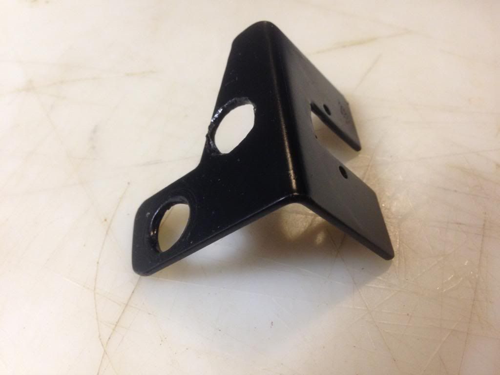
I ordered the Rostra servo, control pad with engagement light, and the mounting bracket from murphskits.com. I cut and drilled the bracket for better fit. It would be easy to make from aluminum angle stock.
My main reference sites were:
• http://users.tpg.com.au/roger38/Rostra%20XT1200Z.htm
• http://www.yamahasupertenere.com/index.php?topic=1820.0
I used this http://users.tpg.com.au/roger38/Rostra%20XT1200Z.htm for inspiration. It was very helpful for wiring and electrical connections as well as DIP switch settings on the servo. I don’t think I would have taken this task on without this reference source.
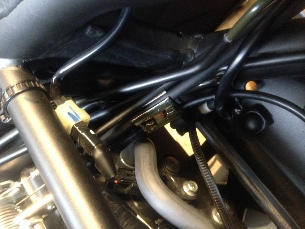
One major change in the wiring is that the light green wire used for the VSS leaves the servo, enters a wiring bundle on the wiring harness and does not come out the other side. I removed the tape from the junction and found the light green wire cut and taped off. I called Rostra and the customer service tech said they no longer use the light green VSS method and recommend using the blue tach/coil wire. The tech stated the function of the light green wire is unchanged. I simply extended the light green wire and used it as recommended by Gary (SuperCruise on Advrider)
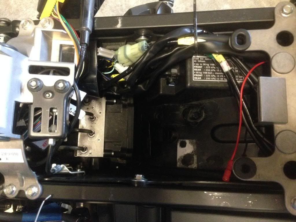
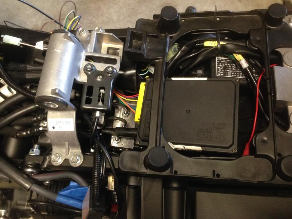
I used this http://www.yamahasupertenere.com/index.php?topic=1820.0 for installing the servo under the seat. I used a heat gun to soften and flatten the “bumps” in the plastic tray and the Rostra servo fits snuggly. It looks like it belongs in this location. I will probably cut and refit the plastic shield for the ABS unit but this is not necessary.
 INSERT TRAY PHOTOS HERE
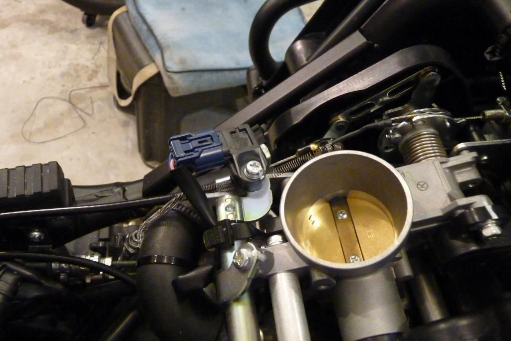
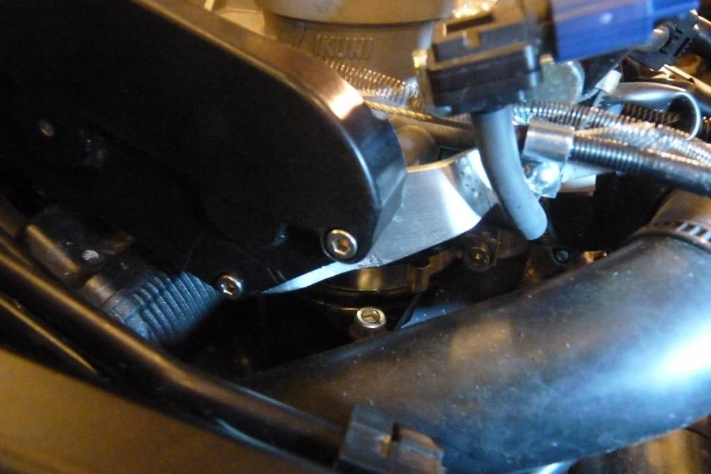
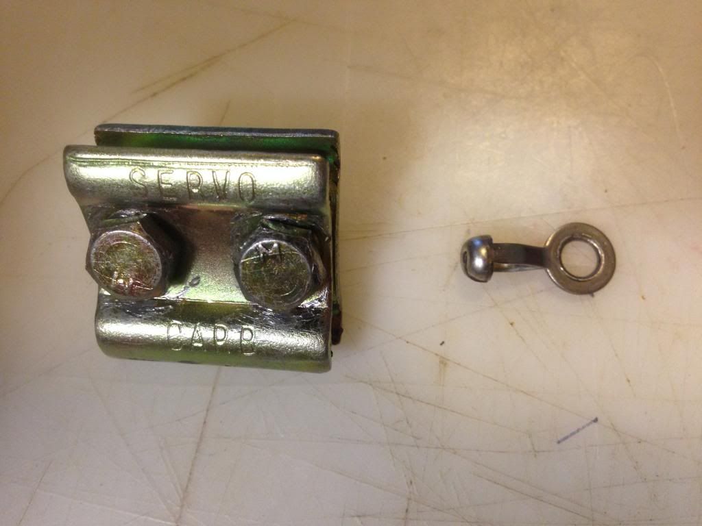
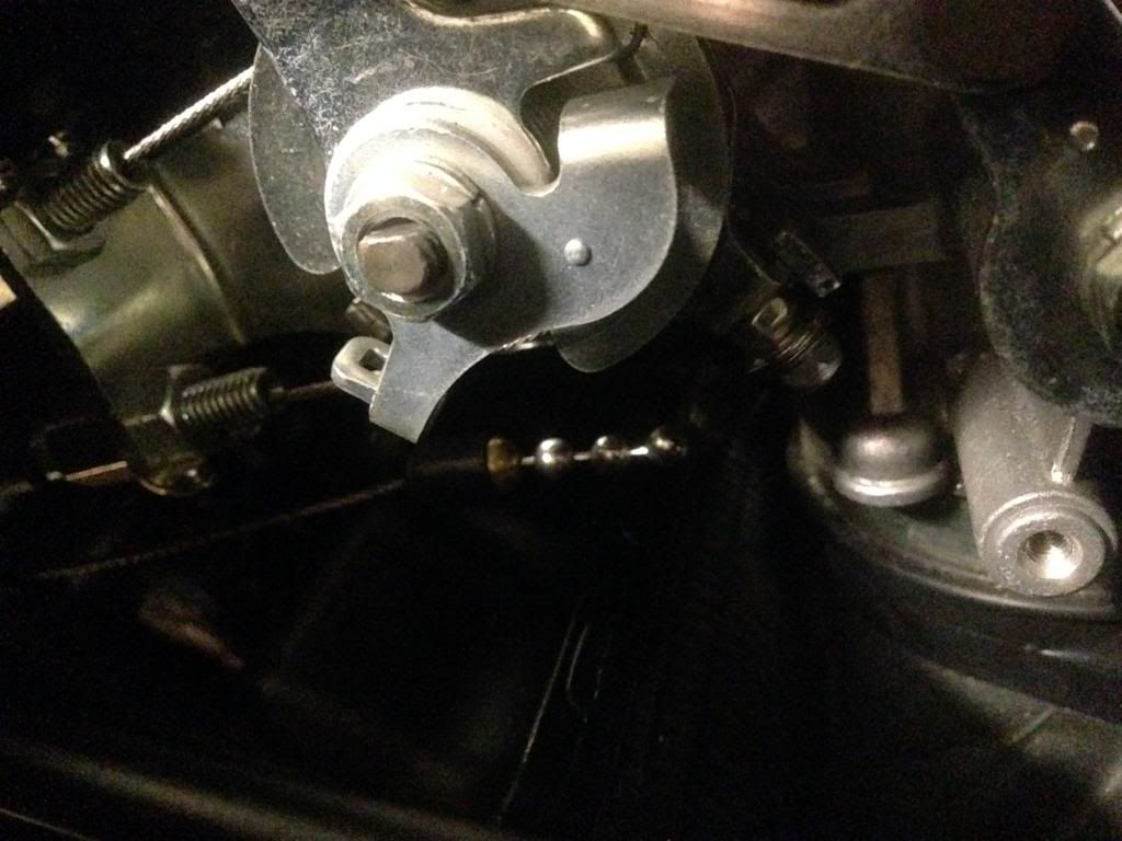
Connecting the servo cable to the throttle bell crank was the part of installation that caused me the most anxiety. I used a different approach from the other write-ups. I have installed several Audiovox vacuum servo cruise control units and had parts left over. One of the left over parts was a clamp that mounts the servo cable parallel to the throttle cable. I used this to clamp the servo cable to the throttle cable.
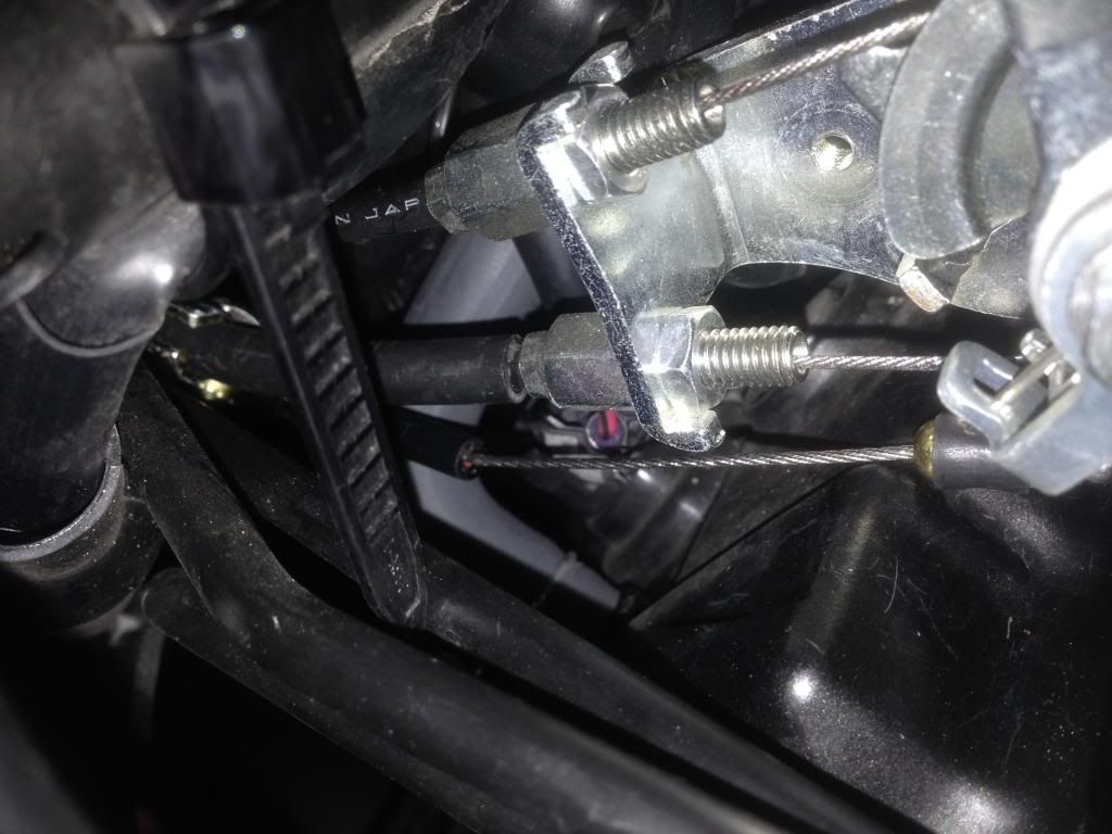
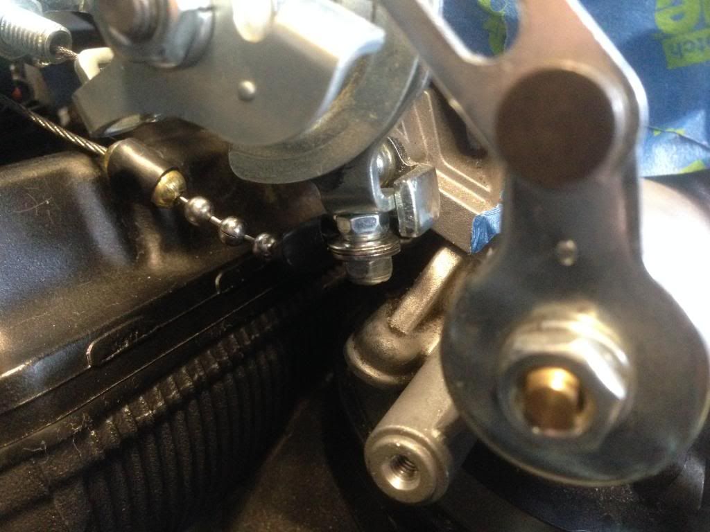
The servo cable was attached to the ball chain with 3 balls showing, five balls total. This was calculated using directions in the manual given the measured movement of the throttle bell crank. The ball chain was attached to the smallest eyelet connector included with the servo. I drilled a small hole in the bell crank idle stop. I put a 4-40 screw through the hole, attached it to the idle stop with a nylock bolt, the eyelet over the nylock 4-40 bolt, a washer, and finally another nylock nut. I did not tighten the final nylock nut against the eyelet. I left slight clearance so the eyelet can move freely. The nylock does not have to be torqued against a surface to stay in place, I hope :-\. I used a fresh unused nylock for the final assembly. The slight clearance allows slight movement and relieves stress. The fit is close and the 4-40 screw needs to be as short as possible. The “stack” is: 4- 40 screw, bell crank, nylock nut, eyelet, washer, nylock nut. this was a PIA. I messed with this for a long time to assure myself it would work safely without hanging up or binding.
I decided how I wanted to install the servo cable. Other's have done it differently. You have to make your own choice. Your bike your decision.
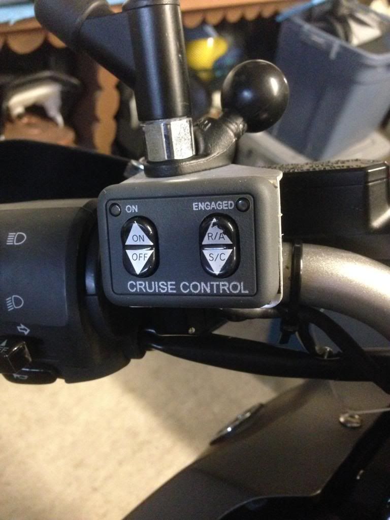
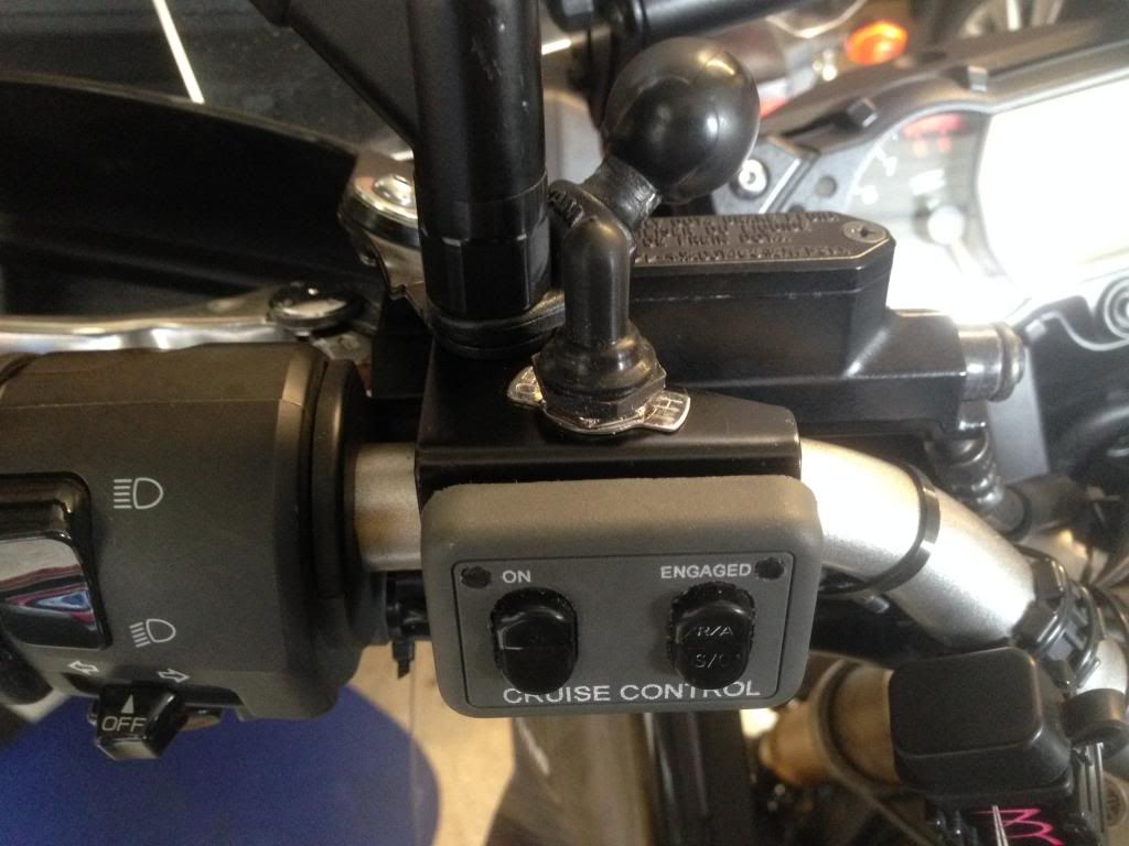
I also installed the optional control switch with the engaged light. This requires the orange wire from the servo. Rostra also cut and taped off this wire. I extended this wire to the relay needed for the engaged light. I followed the instruction included with the control pad. I installed the engaged indicator light relay behind the servo. I like the engaged indicator light but am not sure it was worth the effort. I sealed the control pad with acid free silicon fish tank sealant. Fish and electronics don't like acid sealant. Be careful not to overdo this as the sealant might make the switches too stiff. I learned this the hard way
Brackets from Murphskits and fabricated from aluminum angle stock
The cruise control engages smoothly without hesitation. It holds speed +- 1 mph on most roads and on roads with climbs and descents normally holds within 1-2 mph. It briefly and rarely varies 3 mph when the road slope changes dramatically. It works as well as a car cruise control down to about 50 mph in sport mode and down to 35 mph in tour mode. I have the Gen 2 reflash. It will hold steady at any speed I have tried ::013:: I have been on a couple of 200 mile rides without problems. Time will tell ::001::
Working on this sure makes the 2014 Super Tenere with OEM cruise look good.
I ordered the Rostra servo, control pad with engagement light, and the mounting bracket from murphskits.com. I cut and drilled the bracket for better fit. It would be easy to make from aluminum angle stock.
My main reference sites were:
• http://users.tpg.com.au/roger38/Rostra%20XT1200Z.htm
• http://www.yamahasupertenere.com/index.php?topic=1820.0
I used this http://users.tpg.com.au/roger38/Rostra%20XT1200Z.htm for inspiration. It was very helpful for wiring and electrical connections as well as DIP switch settings on the servo. I don’t think I would have taken this task on without this reference source.
One major change in the wiring is that the light green wire used for the VSS leaves the servo, enters a wiring bundle on the wiring harness and does not come out the other side. I removed the tape from the junction and found the light green wire cut and taped off. I called Rostra and the customer service tech said they no longer use the light green VSS method and recommend using the blue tach/coil wire. The tech stated the function of the light green wire is unchanged. I simply extended the light green wire and used it as recommended by Gary (SuperCruise on Advrider)
I used this http://www.yamahasupertenere.com/index.php?topic=1820.0 for installing the servo under the seat. I used a heat gun to soften and flatten the “bumps” in the plastic tray and the Rostra servo fits snuggly. It looks like it belongs in this location. I will probably cut and refit the plastic shield for the ABS unit but this is not necessary.
Connecting the servo cable to the throttle bell crank was the part of installation that caused me the most anxiety. I used a different approach from the other write-ups. I have installed several Audiovox vacuum servo cruise control units and had parts left over. One of the left over parts was a clamp that mounts the servo cable parallel to the throttle cable. I used this to clamp the servo cable to the throttle cable.


The servo cable was attached to the ball chain with 3 balls showing, five balls total. This was calculated using directions in the manual given the measured movement of the throttle bell crank. The ball chain was attached to the smallest eyelet connector included with the servo. I drilled a small hole in the bell crank idle stop. I put a 4-40 screw through the hole, attached it to the idle stop with a nylock bolt, the eyelet over the nylock 4-40 bolt, a washer, and finally another nylock nut. I did not tighten the final nylock nut against the eyelet. I left slight clearance so the eyelet can move freely. The nylock does not have to be torqued against a surface to stay in place, I hope :-\. I used a fresh unused nylock for the final assembly. The slight clearance allows slight movement and relieves stress. The fit is close and the 4-40 screw needs to be as short as possible. The “stack” is: 4- 40 screw, bell crank, nylock nut, eyelet, washer, nylock nut. this was a PIA. I messed with this for a long time to assure myself it would work safely without hanging up or binding.


I decided how I wanted to install the servo cable. Other's have done it differently. You have to make your own choice. Your bike your decision.
I also installed the optional control switch with the engaged light. This requires the orange wire from the servo. Rostra also cut and taped off this wire. I extended this wire to the relay needed for the engaged light. I followed the instruction included with the control pad. I installed the engaged indicator light relay behind the servo. I like the engaged indicator light but am not sure it was worth the effort. I sealed the control pad with acid free silicon fish tank sealant. Fish and electronics don't like acid sealant. Be careful not to overdo this as the sealant might make the switches too stiff. I learned this the hard way
Brackets from Murphskits and fabricated from aluminum angle stock


The cruise control engages smoothly without hesitation. It holds speed +- 1 mph on most roads and on roads with climbs and descents normally holds within 1-2 mph. It briefly and rarely varies 3 mph when the road slope changes dramatically. It works as well as a car cruise control down to about 50 mph in sport mode and down to 35 mph in tour mode. I have the Gen 2 reflash. It will hold steady at any speed I have tried ::013:: I have been on a couple of 200 mile rides without problems. Time will tell ::001::
")