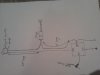
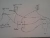
Thanks guys for your help, I don't want to beat a dead horse, I just had to put your info into a drawing, I hope I got it right. For those of you that are more visual like myself here is the drawing I just made.
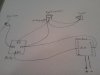
I'm also editing a second drawing, it might also be a correct way when using the Rigid switch. Looking at the harness from Riged I can see that the Riged switch is designed to take the full load. The black (ground wire) is on the switch for its own little red light .
I'm also editing a second drawing, it might also be a correct way when using the Rigid switch. Looking at the harness from Riged I can see that the Riged switch is designed to take the full load. The black (ground wire) is on the switch for its own little red light .
Attachments
-
 19.7 KB Views: 100
 -
 18.2 KB Views: 75


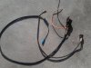
") . The relay is in the same location as Pluric's, up front near the tool bag, the wires go around same place where all the others are except near the tank bolt. Was to tight for the plug to go through so I put under the tank and over the frame with a zip tie.
. The relay is in the same location as Pluric's, up front near the tool bag, the wires go around same place where all the others are except near the tank bolt. Was to tight for the plug to go through so I put under the tank and over the frame with a zip tie.