Final-Drive Leaking, Seal Replacement

SkunkWorks

Well-Known Member
Joined
Sep 13, 2018
Messages
1,784
Location
Colorado
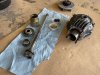
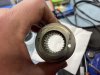
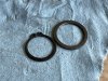
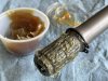
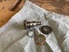
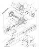
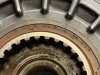
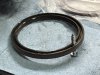
Next, I moved on to the Output-Seal.

This is the Yamaha part-number.
IMG_7252.JPG

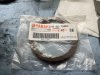
Not sure what manufacturer brand this is, but is the same on both the old and new Seals

IMG_7249.JPG

The Part-Numbering on the old Seal.

IMG_7251.JPG
IMG_7250.JPG

Part-numbering on the new Seal.
The only difference here is the "A1" vs the "A4" on the old one. This is most likely a manufacture-date (ie: Month, Week, Day, Year, etc......)
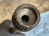
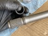
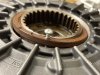
I can confirm the numbers refer to the ID, OD, and thickness in MM.....................I measured the old one.
70mm x 84mm x 6mm
IMG_7258.JPG

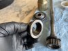
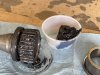
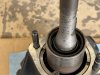
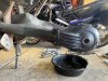
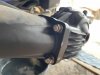
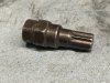
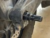
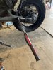
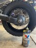
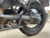
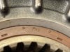
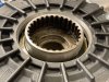
Removing the old one:

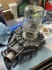
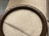
I drilled a tiny hole in the exposed face of the old Seal.

IMG_7253.JPG

I threaded in a small sheet-metal screw.
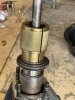
As you tighten the screw it bottoms against a large metal washer, that sits just outside of the output-bearing.
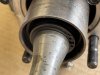
Further tightening just pushes the Seal out, and did not require much force at all.

IMG_7254.JPG

IMG_7255.JPG

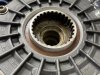
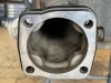
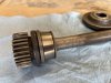
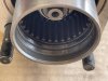
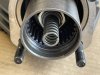
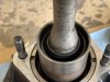
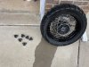
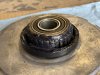
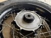
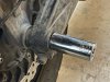
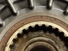
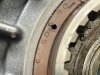
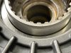
With the Seal out, you can see the large washer behind it.

IMG_7256.JPG

I wiped everything clean before starting to install the new Seal.

IMG_7257.JPG
 

SkunkWorks

Well-Known Member
Joined
Sep 13, 2018
Messages
1,784
Location
Colorado
I searched around the Garage for something that was the right diameter that I could use to seat the new Seal.
Without any luck there, I extended my search to the Kitchen.
It turns out, a wide-mouth Mason-Jar is exactly the right diameter to use for this!

IMG_7259.JPG

I wiped a film of wheel-bearing grease on the lip of the Seal, and used the Mason-Jar and a rubber-mallet to seat it in place.
I then returned the Mason-Jar to the Kitchen Cabinet, and my Wife was none the wiser............. :p

IMG_7260.JPG

Fully Installed!

IMG_7261.JPG

Next-Up is cleaning up the Swingarm, mating the Driveshaft with the Coupler, and re-installing the whole assembly back on the Bike.
Then I can fill it with fluid, finish up some other maintenance on the Bike, and go for a test-ride!
 

SkunkWorks

Well-Known Member
Joined
Sep 13, 2018
Messages
1,784
Location
Colorado
Cleaned all the excess gear-oil and dust out of the end of the Swingarm.
I shined a light up inside, and it was clean all the way to the front.
I made sure the little drain hole was clear of any dirt.

IMG_7266.JPG

Layed out the items to go back together, as well as the Tools I would need to put the shaft-seal back inside the Drive-Coupler.

IMG_7267.JPG

This is an old inner Race from a cone-bearing that I saved from something in the past.
I save a whole bunch of these..................different sizes...................they come in handy for times like this.

IMG_7268.JPG

It is the perfect diameter for installing this Seal.

IMG_7269.JPG

This seal gets pressed into the end of the Drive-Coupler, and seats into the area shown here.

IMG_7270.JPG

Now why would there need to be a Seal installed here, when it's just a greased spline interface you ask?
Well.................it's because these splines are actually lubricated with gear-oil from inside the Housing...
There are two small holes in the housing end of the Drive-Coupler that are open to the gear-oil.
These 2 small holes shown here.
IMG_7234.JPG

Yama specifies Moly-grease on these splines also.................so I applied some.
IMG_7271.JPG

Don't forget this little Spring.
It attaches to the end of the pinion-shaft.
IMG_7272.JPG

It goes inside this hole in the end of the Driveshaft.
It keeps forward pressure into the Universal-Joint all the way at the front, since that is just a splined slip-fit.
I'm guessing it also absorbs some of the driveline shock during hard suspension hits.
IMG_7273.JPG
 

SkunkWorks

Well-Known Member
Joined
Sep 13, 2018
Messages
1,784
Location
Colorado
Once I insert the driveshaft splines into the Coupler, I then use my bearing race and a ball-joint adapter to tap it in place with my Fork-Seal driver Tool.

IMG_7275.JPG

IMG_7276.JPG

Fully seated.
IMG_7277.JPG

Next is to install the Washer and Snap-Ring on the Driveshaft, to keep this Seal from walking its way out and down the Shaft.
IMG_7278.JPG

IMG_7279.JPG

Followed by this little Snap-Ring that goes at the front of the Shaft.
This keeps the Driveshaft from moving too far forward in the front U-Joint.
IMG_7280.JPG

Applied the specified Lithium grease to the front Splines.
IMG_7281.JPG

And then slid the whole assembly up into the Swingarm, making sure to engage the Splines with the U-joint coupler way up inside there.
IMG_7282.JPG

I then installed the 4 Washers and Capped-Nuts onto the Studs holding it to the Swingarm.
I barely snugged them just to the point of contact........................I will come back and torque them later.
IMG_7283.JPG

IMG_7286.JPG
 

SkunkWorks

Well-Known Member
Joined
Sep 13, 2018
Messages
1,784
Location
Colorado
I degreased and scrubbed the back wheel and tire........................Man was it filthy!

IMG_7285.JPG

Apply some Moly-grease to the Splines of the Cush-Drive Plate
IMG_7284.JPG

And install it along with the Rubber Dampers into the Wheel.
IMG_7287.JPG

And DO NOT forget this Spacer-Sleeve.
It goes inside the Output-Drive gear before you mount the Wheel to it.
IMG_7288.JPG

Next comes mounting the Wheel assembly, ABS sensor-Plate, Brake Caliper-Bracket, and Washer.
Slide the Axle through the whole Stack, and then torque to 90 ft/lbs while holding the other side with the Axle-tool.
IMG_7289.JPG

I use this Splined Tool....................................I think it fits some sort of Volkwagen Axle application?
I've had it so long, I don't remember exactly..............
IMG_7304.JPG

The smaller Hex is 19mm, and fits the end of the Axle
IMG_7305.JPG

The other Hex is 21mm.
I just use a deep-socket over that.
Don't forget to tighten the axle Pinch-Bolt after you torque the Axle nut.
IMG_7307.JPG

Next, I go back and torque the Capped-Nuts on the Swingarm.
Yamaha specifies 30 ft/lbs on these.
IMG_7290.JPG

Yamaha also says to torque these before mounting the Wheel.................
I like to make sure the Gear-Housing is "clocked" in the correct position with the Axle first, so I mount and torque the Wheel and Axle before tightening these to their final value.

Lastly I inspected the Brake Pads before putting them back in place and mounting the Caliper to the bracket.
Install the ABS wheel-sensor and tighten the caliper Torque-Arm bolts.
 

SkunkWorks

Well-Known Member
Joined
Sep 13, 2018
Messages
1,784
Location
Colorado
All back together!
Ready for another 46,000-miles hopefully...........

IMG_7292.JPG

IMG_7291.JPG

Filled the Final-Drive with Valvoline Synthetic 75w90 until it started running out of the fill-hole.
IMG_7295.JPG

I then moved onto a few other Pre-Season maintenance items.

Cleaned and greased both the Shifter Pivot, and the rear-brake Lever Pivot.
IMG_7293.JPG

While I was under there I also removed, cleaned, and greased the side-stand Pivot.
It was a bit gritty in its operation.
IMG_7294.JPG

Lastly was Engine Oil and Filter change.
I already had two qts of 10w50 leftover from a previous job, so I added two qts of 10w40 to it........................I'm going with 10w45 Castroline this time! :p
IMG_7296.JPG
 
Last edited:

SkunkWorks

Well-Known Member
Joined
Sep 13, 2018
Messages
1,784
Location
Colorado
Went out for a nice Shakedown Ride today!

Stopped for lunch at Zoka's
IMG_7298.PNG

IMG_7299.JPG

Zoka-Burger and Fries, with an IPA
IMG_7300.JPG

134 Miles
Mostly pavement with a little bit of dirt-road mixed in there.

IMG_7302.PNG

IMG_7303.PNG

Final-Drive Housing is Dry and Leak-Free.....................Success!
I even double-checked the drain-hole to make sure nothing coming out of there.
IMG_7301.JPG

So here's the Parts you will need to replace if you have to do this job.
Most likely you will not find these in stock anywhere, and you will have to order them.
It's up to you if you want to pre-order them to have on hand just in case.

From this Diagram you will need:

#14 Input Seal - Yamaha part number: 93102-50009-00 (alternatively: SKF part number: 19601, which is what I used)
#25 Output Seal - Yamaha part number: 93102-70004-00

Yamaha also specifies replacing the Nut that holds the Coupler onto the pinion-shaft. This nut uses a 27mm Socket, which is the same as the rear Axle-Nut.
#17 Nut - Yamaha part number: 90179-20015-00
And also the Seal that is on the end of the Driveshaft that fits into the Coupler.
#39 Oil Seal - Yamaha part number: 93108-49003-00
I re-used both of these parts, but I will have them on the shelf if I ever have to do this job again.

You do not have to remove #12 - Bearing Retainer to remove the Input Seal. (the Input Seal is actually seated inside this Bearing Retainer, and bottoms against a lip down inside of it)
If you do remove it, you will also need the O-ring #13,
Screenshot 2024-03-31 215849.jpg

If you remove two of the Torx Bolts and lock the Cush-Drive Plate to the Housing like I did, you will need a T-40 Torx Bit.

Feel free to message me or post up here if you have any other questions regarding replacing these Seals.
 
Last edited:

SkunkWorks

Well-Known Member
Joined
Sep 13, 2018
Messages
1,784
Location
Colorado
curious , how many hours start to finish ? if I only had a shop/garage ....
I would say total work time for me was probably about 3 hours, but a lot of that time was spend cleaning things before/during removal.
Some of that was spent fabricating and/or finding the right Tools also.

You could do it quicker if you already had the correct Tools, ready to go.
 
Top