RCinNC
Well-Known Member
I’ve been using my Zumo XT for a little over a year now, and like it. After many miles on bad dirt and gravel roads, I did develop some concerns about the mount, though I’ve never actually had the Zumo unintentionally disengage. The unit is held in the mount with a spring loaded plastic tab which, if it failed or wasn’t properly engaged, would cause the unit to just flop out of the mount and go on a journey of its own. It also vibrates a bit on rough roads, which isn’t surprising with a heavy unit attached to a ball mount that acts like a lever.
I didn’t want to attach something like a lanyard to the unit. Even with a lanyard the unit can still come off the mount and bang around the bike until you can get stopped. I wanted to keep the powered mount supplied with the Zumo (and not use USB power or rely just on the battery), so I can keep the unit always powered up and still retain its waterproof features. I also wanted to bring the unit closer in line with the accessory rail to eliminate some of the vibration that occurs when the unit is further from the rail, the way it is when it’s on a RAM ball mount. The following photos are what I came up with.

The mount body is made up of a layer of .090 and .125” ABS sheet, laminated together. There’s a channel in the center of the mount body that allows the top clamp to slide up and down. The face plate is made of a piece of .080” aluminum sheet. The combination of aluminum and ABS makes for a very rigid structure.
The top clamp was made from a piece of .080” aluminum sheet, bent on a small 4” bending brake that fits in my vise. The bottom clamp is fashioned from a piece of 1 ½” x 1 ½” x 1/8” aluminum angle from the hardware store.
The accessory rail clamp was made from a laminated block of ABS. There’s a lot of clamping force exerted on a mount like this when you tighten it, so the mount has to be pretty rigid or else it’ll bend around the rail. The mount body provides added strength for the inside half of the mount. For the outside half, I made a cap from a piece of 5/32” aluminum plate. This cap makes the ABS mount rigid enough to prevent the mount from bending.
The rubber anti-slip pads shown on the bottom clamp grip the Zumo housing and prevent it from sliding to either side when the bottom and top clamps are in the closed position. There are similar pads on the top clamp.

This photo should give a clear idea of how the mount works. The top clamp can slide up and down inside the body of the mount. The bottom clamp is able to slide up and down via two slots on the clamp. These slots are hard to see in the other photos, so here’s a closer photo of them:

The position of both the top and bottom clamp is fixed by moving the clamps into position against the Zumo, and tightening those three knobs on the front of the mount. The knobs thread into threaded inserts inside the mount body. The threaded inserts are simply stainless steel machine nuts embedded in the plastic body of the mount.
The main purpose of the top and bottom clamps isn’t to support the Zumo (though they could accomplish this). They’re designed to trap the Zumo so it can’t move even if the Zumo mount totally fails. The clamps are designed to touch the Zumo, but they aren’t clamped to it with any force. In order for the Zumo to be removed from its powered mount, it has to pivot forward to remove the bottom of the unit from the mount. It can’t pivot when the lower clamp is in place. The top clamp also prevents the Zumo from pivoting forward. Both the top and bottom clamps have lips on them that prevent the unit from being pulled forward out of my mount, and the rubber anti-slip pads keep the Zumo from sliding sideways out of the mount.

The Zumo power cable has to exit from the bottom of the Zumo mount. In order for the bottom clamp to be able to move up and down, the cable has to be able to pass through the bottom clamp, so I cut a slot in the bottom clamp to allow this movement.
You can see in the above photo that the adjustment knobs on the bottom clamp stick out pretty far from the mount. This is by design. If the knobs were directly under the bottom clamp, they’d be in such a tight space that it would be hard to manipulate them, especially with gloves on. The knobs are also too large to allow enough clearance for the bottom clamp to move far enough, if the knobs were directly under the clamp.
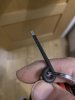
The knobs were probably the most finicky part of the design. I couldn’t find a commercial version that was the right length, thread size and shape, so I had to make them. The knobs were designed to act like shoulder bolts that could be adjusted with your fingers. I made them from stainless steel panhead machine screws, aluminum and plastic tubing, and 3/8” ABS.

Here are all three knobs. When installed, they have split ring washers on them, to keep them from loosening under vibration.

Since I had to route the power cable underneath the mount and over the edge of the lower part of the mount, I wanted to add some protection to the power cable. I put a split piece of vinyl tubing over the cable. This photo also shows the bottom clamp in the closed position and touching the Zumo.

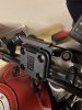
Here’s the Zumo installed in my mount. The mount is in the open position right now.

Here’s the mount in the closed position. Though it may look like it, the lips on the top and bottom clamps don’t interfere with manipulating the screen; they only protrude into the non-active part of the screen.

I took the windscreen off so it wouldn’t obscure the previous photos, but this is how it looks with the windscreen installed:
I try and design these sorts of projects to use flat surfaces and existing readily available aluminum angle. The aluminum angle I used is pretty common at hardware stores, and the .080” sheet came from Amazon. The .090” and .125” ABS sheet also came from Amazon, and the 3/8” block of ABS I used for the knob handles was from an old chunk of it I had laying around from a pannier project on a V-Strom about 10 years ago. I use pretty common hand and power tools (hacksaws, coping saws, files, handheld power tools like a scrollsaw and drill). My most sophisticated hand tool is probably a small tap and die set, and I do have a benchtop WEN drill press.
I made this for a Zumo, but the design would be pretty easy to adapt for guys who want to use the larger tablets as navigation tools.
One minor downside to my design is that you do lose some of the adjustability of an articulated mount like a RAM system. On mine, basically all I can adjust is the viewing angle, and to do this you have to loosen the accessory rail mount and just tilt the mount forwards or backwards. I didn’t have an issue with that, since I found the optimum position for the Zumo on the old mount, and just mimicked those dimensions on the new one.
I didn’t want to attach something like a lanyard to the unit. Even with a lanyard the unit can still come off the mount and bang around the bike until you can get stopped. I wanted to keep the powered mount supplied with the Zumo (and not use USB power or rely just on the battery), so I can keep the unit always powered up and still retain its waterproof features. I also wanted to bring the unit closer in line with the accessory rail to eliminate some of the vibration that occurs when the unit is further from the rail, the way it is when it’s on a RAM ball mount. The following photos are what I came up with.
The mount body is made up of a layer of .090 and .125” ABS sheet, laminated together. There’s a channel in the center of the mount body that allows the top clamp to slide up and down. The face plate is made of a piece of .080” aluminum sheet. The combination of aluminum and ABS makes for a very rigid structure.
The top clamp was made from a piece of .080” aluminum sheet, bent on a small 4” bending brake that fits in my vise. The bottom clamp is fashioned from a piece of 1 ½” x 1 ½” x 1/8” aluminum angle from the hardware store.
The accessory rail clamp was made from a laminated block of ABS. There’s a lot of clamping force exerted on a mount like this when you tighten it, so the mount has to be pretty rigid or else it’ll bend around the rail. The mount body provides added strength for the inside half of the mount. For the outside half, I made a cap from a piece of 5/32” aluminum plate. This cap makes the ABS mount rigid enough to prevent the mount from bending.
The rubber anti-slip pads shown on the bottom clamp grip the Zumo housing and prevent it from sliding to either side when the bottom and top clamps are in the closed position. There are similar pads on the top clamp.
This photo should give a clear idea of how the mount works. The top clamp can slide up and down inside the body of the mount. The bottom clamp is able to slide up and down via two slots on the clamp. These slots are hard to see in the other photos, so here’s a closer photo of them:
The position of both the top and bottom clamp is fixed by moving the clamps into position against the Zumo, and tightening those three knobs on the front of the mount. The knobs thread into threaded inserts inside the mount body. The threaded inserts are simply stainless steel machine nuts embedded in the plastic body of the mount.
The main purpose of the top and bottom clamps isn’t to support the Zumo (though they could accomplish this). They’re designed to trap the Zumo so it can’t move even if the Zumo mount totally fails. The clamps are designed to touch the Zumo, but they aren’t clamped to it with any force. In order for the Zumo to be removed from its powered mount, it has to pivot forward to remove the bottom of the unit from the mount. It can’t pivot when the lower clamp is in place. The top clamp also prevents the Zumo from pivoting forward. Both the top and bottom clamps have lips on them that prevent the unit from being pulled forward out of my mount, and the rubber anti-slip pads keep the Zumo from sliding sideways out of the mount.
The Zumo power cable has to exit from the bottom of the Zumo mount. In order for the bottom clamp to be able to move up and down, the cable has to be able to pass through the bottom clamp, so I cut a slot in the bottom clamp to allow this movement.
You can see in the above photo that the adjustment knobs on the bottom clamp stick out pretty far from the mount. This is by design. If the knobs were directly under the bottom clamp, they’d be in such a tight space that it would be hard to manipulate them, especially with gloves on. The knobs are also too large to allow enough clearance for the bottom clamp to move far enough, if the knobs were directly under the clamp.
The knobs were probably the most finicky part of the design. I couldn’t find a commercial version that was the right length, thread size and shape, so I had to make them. The knobs were designed to act like shoulder bolts that could be adjusted with your fingers. I made them from stainless steel panhead machine screws, aluminum and plastic tubing, and 3/8” ABS.
Here are all three knobs. When installed, they have split ring washers on them, to keep them from loosening under vibration.
Since I had to route the power cable underneath the mount and over the edge of the lower part of the mount, I wanted to add some protection to the power cable. I put a split piece of vinyl tubing over the cable. This photo also shows the bottom clamp in the closed position and touching the Zumo.
Here’s the Zumo installed in my mount. The mount is in the open position right now.
Here’s the mount in the closed position. Though it may look like it, the lips on the top and bottom clamps don’t interfere with manipulating the screen; they only protrude into the non-active part of the screen.
I took the windscreen off so it wouldn’t obscure the previous photos, but this is how it looks with the windscreen installed:
I try and design these sorts of projects to use flat surfaces and existing readily available aluminum angle. The aluminum angle I used is pretty common at hardware stores, and the .080” sheet came from Amazon. The .090” and .125” ABS sheet also came from Amazon, and the 3/8” block of ABS I used for the knob handles was from an old chunk of it I had laying around from a pannier project on a V-Strom about 10 years ago. I use pretty common hand and power tools (hacksaws, coping saws, files, handheld power tools like a scrollsaw and drill). My most sophisticated hand tool is probably a small tap and die set, and I do have a benchtop WEN drill press.
I made this for a Zumo, but the design would be pretty easy to adapt for guys who want to use the larger tablets as navigation tools.
One minor downside to my design is that you do lose some of the adjustability of an articulated mount like a RAM system. On mine, basically all I can adjust is the viewing angle, and to do this you have to loosen the accessory rail mount and just tilt the mount forwards or backwards. I didn’t have an issue with that, since I found the optimum position for the Zumo on the old mount, and just mimicked those dimensions on the new one.