STS Smart Turn self-canceling turn system thingy review

WJBertrand

Ventura Highway
Joined
Jun 20, 2015
Messages
4,532
Location
Ventura, CA
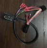
Bought one of these a year ago (https://www.safer-turn.com/us/) and finally got around to pulling it off the bench and installing it this weekend.

This is a pretty cool little gadget and it works really well, brilliantly in fact. It's even sensitive enough to detect a lane change unless you just kind of drift lanes and don't make any kind of positive steering movement, even then it'll time out after 30 seconds or so. When making a real turn it cuts the signal just as the bike comes back to vertical after the turn. The lane change feature seems to blink one or two more times than I would if canceling manually as I found myself punching the cancel switch to no effect. Since you defeat the "latching" of the OEM switch with some little foam pads (supplied). Manually canceling it in the normal way doesn't work. Took me a few miles to figure out that you have to push the switch again in the same direction to cancel manually. There will hardly ever be a need to do that however.

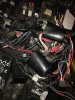
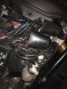
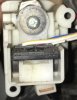
STS Could do a lot better with the instructions though. Making model specific instructions, or even plug 'n' play kits, would be a lot of work on their end but it would have saved my a ton of time at my end. Took me an hour or so to identify the correct connector for the turn signal switch harness. The wire colors in their generic downloadable instructions were incorrect for Yamaha, at least for the Super Tenere anyway. Between the service manual and disassembling the left switch pod (which you must do anyway to insert the little foam anti-latching pads) I was finally able to confirm the wire colors and locate the connector under the right side electrical panel. I also had to play with the my VOM quite a bit to confirm which side of the connector led to the switch pod and which side led into the bike's electrical system - it makes a difference hooking up the STS. I also confirmed which wire was left and right measuring the voltage with the switch turned on. Interesting, even though the signal lights are blinking, the voltage remains constant. I guess that makes sense as the flasher module is further buried in the system someplace. The good news is that now I've done all that work for future reference, at least for the Super Tenere and perhaps other Yamahas.

There's a thread over at ST-Owners about this device installation, mostly it seems on 1300s. On that bike you need to make an additional connection to preserve the 4-way emergency flashers. Yamaha must wire these differently to Honda as the 4-ways were not disturbed. Nice.

I had so much fun watching it cancel automatically all day that I never forgot my signals!
 

spam16v

Active Member
Joined
Aug 11, 2014
Messages
336
Location
B-low, NY
Can you expand on what was necessary to install this? I’d be interested in one of these myself.
 

Thrasherg

Active Member
Joined
Oct 16, 2017
Messages
321
Location
Dallas, TX
I would be interested in more details also. I bought one, but then it stated that I have to open up the switch on the handlebar control and modify it so the switch always returns to center, as my Tenere is brand new I didn't want to start modifying the switch and risk messing up the warranty, but the instructions gave no idea if the modification is trivial or quite involved, so due to the complete lack of details I just shelved the unit!! Would be very interested in hearing a lot more details and any pics you might be willing to share. If it does work well i would like to fit one to my wife's FZ07 also, but again for the minute I didn't want to mess about with the mechanics of the indicator switch until I better understood what is involved.

Gary
 

WJBertrand

Ventura Highway
Joined
Jun 20, 2015
Messages
4,532
Location
Ventura, CA
spam16v said:
Can you expand on what was necessary to install this? I’d be interested in one of these myself.
Fennellg said:
You are the only one I have found that got one working on a Super Tenere. Pics or video would be nice. There is a lot of interest. A more detailed write up on how you got this done would be fantastic. What year is your bike?

::020::
Sure, it's not too hard and I'm happy to share what I learned. If I were to do this again I would disassemble the left switch housing first to confirm the wire colors going to the turn signal switch. You have to open the switch at some point anyway to insert the little foam pads that prevent the switch from latching.
There are three wires. a blue w/red stripe is the common with W/Y and W/B wires for the left and right signals, at least these were the colors for my 2015 ES California model. Don't know if this scheme varies from year to year or across models. I forget at the moment which is left and which is right, but the information is in the service manual. Look under the right cowl where all the electrical stuff is for a connector containing these three color wires. It's in a large rubber boot just forward of the battery with some other connectors. That connector also contains other wires but we only need the ones that match the colors in the switch. After disconnecting that plug I used my multimeter to demonstrate that the female end leads to the switch, the other end with the male connectors in it leads into the electrical system. It matters which is which for the STS module.

Here's the part many won't like. You have to pull back the outer jacket of the harness about 4" and then cut these three wires. You crimp on the supplied male bullet connectors to the wires coming from the switch side of your cut. Then crimp three female bullet connectors to the other side of the cut that leads into the bike's electrical system. Now connect the STS wires according to the diagram (link below) but ignore the colors of the wires they indicate are for Yamaha, they're incorrect. First connect the red and black wires to a switched 12V source. I used the factory accessory connector buried under the harness just to the rear of the tool kit. Next you connect the three wires with male bullet connectors from the STS module to the three wires you previously crimped the female bullet connectors to that lead into the electrical system. It's important to match the yellow, blue and green wires from the STS to the right, common and left signal wires respectively.

At this point you are supposed to test the unit by switching on the ignition. The left and right signals should each blink once confirming correct connections. After testing you then connect the left, common and right signal wires to the purple, brown & white wires from the STS module respectively.

The module itself needs to be mounted right side up, as level as possible and pointed forward so as not to confuse the IMU inside it. STS says to attach the unit firmly to and directly against the frame if possible. The better the physical contact the better the sensitivity of the unit. In the Super Tenere's case, the STS harness is too short to reach any level places on the frame. I decided to zip-tie it tightly to the plastic electrical tray which seems pretty rigidly mounted to the bike. I placed it high up to the right side of the tray, looking at the bike from the right side with the upper and lower cowls removed. I cut away the plastic rib and drilled four small holes in the plastic is such a way as to hold the unit as level as possible with two zip ties (supplied). The voltage regulator is directly behind this part of the panel so I temporarily removed the two 10mm bolts and moved it away to avoid inadvertently damaging it and to make it easier to thread the tie wraps through the other side of the panel. I snugged it in place, tucked all the wires and harness back where they belong and buttoned her up. The left-right self-check signal flash now occurs every time you turn on the key which is kind of cool.

Functionally the plastic electrical tray seems rigid enough for proper operation. The only iffy bit is if you make very gentle lane changes, sometimes the unit does not detect it. Even so it'll time out after about 30 seconds worst case. I need to test more but changing lanes during a curve may fool the unit sometimes. I.e. rounding a left curve in say the inside lane and then signaling to change to the outside lane. Since you can just let the bike drift out to the outside lane with little to no attitude change, the STS might miss that. The signal can just be allowed to time out, or you can manually cancel by pressing the switch again in the same direction. Since the little foam pads that go in the switch prevent latching, the push in to cancel action no longer works.

I'm terrible about stopping to take photos. I tend to get focused and before I know it I've finished. Not planning to go back under the cowls any time soon but will try to snap a couple of shots if I find myself under there again for some reason. there is a video on the STS site that shows the installation on a different Yamaha. In that video they tap another nearby connector for the 12V source but don't describe how they identified that. Rather than mess with any other circuits, I chose to connect power directly to the accessory connector.

https://www.safer-turn.com/wp-content/uploads/2017/06/STS_install_manual_FINAL_V6.pdf

https://www.youtube.com/watch?v=Pg693JMENfY
 

WJBertrand

Ventura Highway
Joined
Jun 20, 2015
Messages
4,532
Location
Ventura, CA
Thrasherg said:
I would be interested in more details also. I bought one, but then it stated that I have to open up the switch on the handlebar control and modify it so the switch always returns to center, as my Tenere is brand new I didn't want to start modifying the switch and risk messing up the warranty, but the instructions gave no idea if the modification is trivial or quite involved, so due to the complete lack of details I just shelved the unit!! Would be very interested in hearing a lot more details and any pics you might be willing to share. If it does work well i would like to fit one to my wife's FZ07 also, but again for the minute I didn't want to mess about with the mechanics of the indicator switch until I better understood what is involved.

Gary
The little foam pads just slip into a slots already in the switch and stop the switch from latching. It's completely reversible - just pull out the little pads with a tweezer. In the video (link attached to previous post) you can see that step demostrated, the Super Tenere appears to have the exact same switch design as in the video. Very simple.
 

Tenman

Well-Known Member
Joined
Dec 7, 2013
Messages
2,110
Location
Natchez Ms USA
That write up was outstanding. My main problem is. I can't tell colors. How long do you think it would take a mechanic to do it? I HATE taking my bike to a mechanic. The last time I had a mechanic work on a bike. His 14 yro son diidn't tighten my oil plug. After about 10 miles it vibrated out goin around a 50mph curve. I did a full lock powerslide and saved it. SHIT! Oh yeah, the horn was danglin by the wires too.
 

WJBertrand

Ventura Highway
Joined
Jun 20, 2015
Messages
4,532
Location
Ventura, CA
Tenman said:
That write up was outstanding. My main problem is. I can't tell colors. How long do you think it would take a mechanic to do it? I HATE taking my bike to a mechanic. The last time I had a mechanic work on a bike. His 14 yro son diidn't tighten my oil plug. After about 10 miles it vibrated out goin around a 50mph curve. I did a full lock powerslide and saved it. SHIT! Oh yeah, the horn was danglin by the wires too.
Thanks! I think a detail oriented mechanic who is familiar with the Tenere's electrical system could install this in an hour or so. I spent probably 3 or 4 hours at it, but I didn't detail my errors crimping on the bullet connectors. I stupidly put them on the wires backwards and ended up with an auto parts store electrical section visit to source replacements. The biggest problem for me was trying to work out where the handlebar switch harness routing went and which connector to access. Had I opened the switch housing first and looked at the wire colors there, I could have saved myself a lot of time. The second most time consuming thing was figuring out where I wanted to mount the module itself. My choice required a bit of trimming on the plastic electrical tray (easily done). Having worked that all out I could do another one in an hour or hour and half now.

Cycledude said:
If they ever make it plug and play I might buy one.
I gave some feedback to STS about the idea of a plug 'n' play version but they indicate that it would not be possible for them to cover all the different models doing that. I suggested PNP for more popular makes and to continue with the current "generic" model for everything else but have not heard back. I told them I would pay a reasonable premium for a PNP version. They have both a facebook and amazon shop. Perhaps more encouragement from others would motivate them?
 

Thrasherg

Active Member
Joined
Oct 16, 2017
Messages
321
Location
Dallas, TX
I looked at several videos and everyone seems to like the unit, but there were multiple people who did not like the feel of the indicator switch after inserting the foam spacers into the switch. some had the foam fall out, others found the switch became intermittent and others found the switch required a lot of force to make the indicators operate and were worried that the switch would break.
Hows the switch feel on the Tenere?

Gary
 

WJBertrand

Ventura Highway
Joined
Jun 20, 2015
Messages
4,532
Location
Ventura, CA
Thrasherg said:
I looked at several videos and everyone seems to like the unit, but there were multiple people who did not like the feel of the indicator switch after inserting the foam spacers into the switch. some had the foam fall out, others found the switch became intermittent and others found the switch required a lot of force to make the indicators operate and were worried that the switch would break.
Hows the switch feel on the Tenere?

Gary
To me the switch feels the same as OEM, something I was pleasantly surprised by. This may not be true for differently designed switches to what the Super Tenere uses, really can't comment. It might be a slightly harder push but nothing excessive at all and I'm not even sure about that wearing gloves, etc.. I smeared a little film of RTV on the back of the foam pads to possibly help stop them potentially falling out as the slots are on the bottom of the switch assembly, though I'm not sure if that would be an issue or not. I used the thinner of the two different thicknesses provided. You would really have to stuff the thick ones in there on this bike and I could see where that might cause problems.

I will admit initially once or twice not pushing the switch quite far enough to activate the signals, requiring a second stab, but in ~400 miles testing in mixed freeway, in-town and backroads, I've not done it again since. It's sensitivity to lane changes seems a bit inconsistent. In normal straight, vertical riding it is very sensitive to even subtle steering inputs, but is somewhat less sensitive when changing lanes on a curved road where the bike is already leaned over a little bit. It's maybe looking for a more obvious movement in those cases? I'm still studying it however. Perhaps mounting directly against the frame as STS advises might improve this somewhat?
 

Thrasherg

Active Member
Joined
Oct 16, 2017
Messages
321
Location
Dallas, TX
Gigitt said:
I got one and made my own plug and play harness.
I’m yet to install it this weekend.
That is exactly what i want to do, but I didn't know what plug/socket I needed to order to fit the Yamaha wiring loom. Can you tell us/me the plug/socket reference and where you purchased them from? I hate to cut the stock wiring loom.

Regards Gary
 

Gigitt

Active Member
Joined
May 15, 2015
Messages
427
Location
Sydney Australia
Thrasherg said:
That is exactly what i want to do, but I didn't know what plug/socket I needed to order to fit the Yamaha wiring loom. Can you tell us/me the plug/socket reference and where you purchased them from? I hate to cut the stock wiring loom.

Regards Gary
It's not a cheap exercise as you need a good quality roll crimping tool that can do tiny crimps

connector is a 10 position Sumitomo TS025 Sealed Connector - I bought (L) Large wire grommets.
get them here:
https://easternbeaver.com/Main/Elec__Products/Connectors/Sealed/TS025/ts025.html
 

WJBertrand

Ventura Highway
Joined
Jun 20, 2015
Messages
4,532
Location
Ventura, CA
Gigitt said:
It's not a cheap exercise as you need a good quality roll crimping tool that can do tiny crimps

connector is a 10 position Sumitomo TS025 Sealed Connector - I bought (L) Large wire grommets.
get them here:
https://easternbeaver.com/Main/Elec__Products/Connectors/Sealed/TS025/ts025.html
Wondering why you used the bullet connectors instead of just putting all the wires from the STS unit directly into the OEM-style plugs?
 

mike25

Member
Joined
Apr 23, 2013
Messages
34
Location
michigan
All I want is a simple plug and play beeper with a 10 or 15 second delay to remind me
to turn them off.
 

Gigitt

Active Member
Joined
May 15, 2015
Messages
427
Location
Sydney Australia
WJBertrand said:
Wondering why you used the bullet connectors instead of just putting all the wires from the STS unit directly into the OEM-style plugs?
The instruction include a section on initial testing.
You have to have only the bulb/light side connected with power and ground for the initial test to see if you wired it up correctly.

The STS unit has all the connectors already attached (something I hate)
So I just decided to keep using the bullet connectors.
It also allows me to test the harness without the STS connected.
 

Gigitt

Active Member
Joined
May 15, 2015
Messages
427
Location
Sydney Australia
Well I finally installed my unit.

My bridging harness was made with 14cm wire, this worked out quite well as the wires feed down easly to where I mounted the unit.
The STS box has stickers top and bottom so if you are going to use double sided tape to mount it you need to remove the sticker first.
I always use 3M VHB acrylic mounting tape - this tape is super strong.
I mounted the STS box low in the RHS electrical cupboard in front of the battery. This spot very sturdy and does not flex as there is a frame bolt in the same location. This means the STS box has a hard mounting surface. Any flex in the plastic may cause some motion detection errors.
Cabling then routes up and behind all the main harness and is just the correct length to where the harness connection is located. Luck that!

Installing the little rubber discs into the turn switch was not too hard. This is something you HAVE to do else the system will not work.

Pics below
 

Attachments

Top