Installation – Reference the STS Installation Manual, Steps 1-6
On my installation I followed the instructions for the most part but I did not be cut any OEM wires as directed in Step 2 of the instructions and I used different connectors than what was supplied. The only connectors I used that were supplied with the STS were the 2 red male quick disconnect connectors at the end of the STS red and black wires.
I built a jumper to make the connections to the 6 STS wires within the jumper. You just unplug the switch housing connector where it plugs into the bike electrical system and plug in the jumper between the two connectors.
The other 2 STS wires (red and black) are connected to switched 12 V and ground. I just happened to have some matching female quick disconnect connectors that I used to crimp onto wires that I ran down to my PC-8 fuse box.
Step 1
“Locate the cable coming from the left handlebar switch and find an accessible spot.”
They are just telling you to find a good place to cut into the cable coming from the switch, it could be anywhere between the switch and the connector where it plugs into the electrical system on the bike, but I think normally the best place would be just before the connector.
You just want to make sure you got the correct connector and the correct wires.
I think that’s the main thing to get out of this step whether you are going to be making the connections as per the instructions or building a jumper to make the connections.
If you need help
finding the connector, see the notes on
Gen 1 and Gen 2 differences in the reply above.
The
wire colors for the 3 wires that you will need can be found in the wire color chart in the STS Installation Manual.
You should still confirm for yourself that you have located the correct wires.
flasher/Hazard Relay wire – Probe the back of the connector with a multimeter to confirm that you have 12 V flashing power when the signals are activated.
Left and Right signal wires – Disconnect the switch housing connector from the bike electrical system. Open the switch housing on the handlebar to access the signal switch. Look inside the signal switch (where the foam pads will go) there is a contact point for both right and left blinker. Position the switch for a right turn to expose the contact point for the left signal. Now you can use the multimeter to check continuity from the contact point to the end of the wire at the connector to confirm the color of the wire. Then use the same method to check the wire for the right signal.
Steps 2 -5
I did Step 6 next and then came back and built the jumper as I went through Steps 2-5.
I made the connections as per the instructions, I was just using different connectors.
The jumper will have wires that are jumpered straight across between the connectors for the wires that are not used in the STS installation. The 3 wires that are to be cut according to the STS instructions will not have jumper wires between the connectors in those 3 positions, so in effect they are cut.
Also, if there is a blank position in your OEM connector, there is no need for a jumper wire in that position either.
I will post some more information on building the jumper in another reply.
The only issues I had in Steps 2-5 are what I discussed in the reply above, on the right signal short flash and the positioning of the foam pads.
NOTE:
See the next reply below, I added some more information on taking the switch housing apart and inserting the foam pads in the signal switch. Also some info on confirming the wires colors by using the terminals inside the signal switch.
Step 6
“Attach the STS unit to firm mounting spot. Logo must be pointing upwards and arrow in driving direction.”
See more information on the back page of the instructions, in the section
Attach STS unit to firm mounting spot.
I wanted to find a good place to mount the STS and see how I would route the cable before I did anything else.
Since I was building a jumper to do my installation I also wanted to see where my jumper plugs would be located and if the loose wires at the end of the STS cable were long enough.
I cut another inch off the outer insulation on the STS wiring harness so I had 4” of loose wire at the end. This gives you better flexibility to position the jumper connectors when the STS wires are attached.
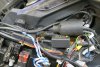
See Picture below.
You can see, there should be enough cable length to mount the STS about anywhere you want in the electrical area. The STS is at the top of the picture and the end of the wiring harness is at the bottom.
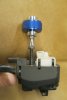
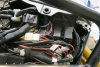
I think this is a good place to mount it, on the top shelf above the electrical tray.
This shelf slopes down then back up to form a V shape. The STS needs to be level, as required by the instructions, so you could place it in the saddle of the V and make it level by resting the corners on the sides of the V.
The only problem is I have already used that space for other stuff. There is a Heat Troller module for my heated grips that is secured with the 2 zip ties, under the twisted blue and white wires in the picture. That will need to be moved to the left. There is also wiring from other accessories in the V.
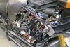
This shows an uncluttered view of the V shape area on the top shelf. (not my picture, just one I found)
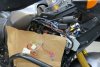
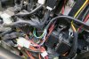
I got the Heat Troller module moved to the left and secured the STS cable with a zip tie. I just reused the hole I had drilled for the Heat Troller. I could not rest the right side of the STS on the other side of the V like I wanted, my other wiring was in the way and I did not want to move it so I just rested it on a piece ½” CPVC pipe then secured the CPVC with a zip tie. I thought I would need to secure the STS with another zip tie across the top but it seemed secure as it was. It is very light so it should be ok.
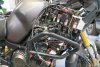
This shows the routing of the cable.
I left the end of the STS cable loose until I had all the terminals crimped onto the STS wires and inserted in the jumper connectors.
The cable was secured with a zip tie just before the end of the black insulation.
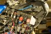
This shows the jumper plugged into the OEM connectors. The STS red and black wires with the red connectors are plugged into my blue connectors that go to the 12V switched and ground in the PC-8 fuse box.
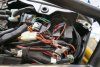
This just shows the jumper all pushed back into position and wires tucked in out of the way
")