kjetil4455
Active Member
Dear friends
I wanted to post this briefly, as I think many are on the fence about flashing their bikes due to waiting times. Especially those of you, as I, who are not living near the flashing shops and would have to wait weeks if not months to get your ECU chip back.
Well, I read a lot about flashing services, and I really liked what was being said about 2wheeldynoworks. I contacted them and said that although I am no bike expert, I am quite techy and I wonder if I can do this myself. I quickly received a response that, yes, indeed, I would just have to purchase the flashing gear (about 380 bucks) and the custom flash map that they sell (about 250 bucks), and they'd send it down here. I could reflash my bike as many times as I wanted, and any updates to their mapping would be free for the future. So I did that.
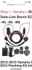
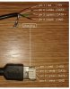
Here are the links for the flashing gear:
* https://2wheeldynoworks.com/products/12-13-yamaha-xt1200-super-tenere-data-link-ecu-flashing-kits (my bike is 2012. Make sure you choose the right gear for your bike's year)
* https://2wheeldynoworks.com/products/2wdw-custom-ftecu-mapping
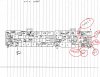
They will ask you for your ECU PART NUMBER AND ECU SERIAL NUMBER. You won't receive the flash maps until you provide this.
For brevity, if anyone's interested, here's what sparked my interest in this company's specific flashing service (copy paste from another member's statement on here):
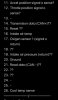
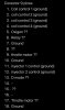
- Disable ais - no more decel popping (valve always closed via ecu disable)
- Smode: 1:1 linear throttle with no power restrictions in any gears
- Tmode: sub 1:1 throttle below 50% throttle with smoothing down low. Above 50% throttle and T mode becomes S mode (identical fueling)
– Disable Injector Decel Cut
– Professional fuel map modification for my aftermarket exhaust
– Removal of all gear based or speed dependent restrictions, TRE
– Optimized timing maps for 91+ octane
– Reduce Fan Temps 205°F
– Bypass EXUP Valve (if the tenere has it, cant remember)"
In my case, I asked for mapping specific for shitty fuel as the octane here (in Colombia) is low. I also have an arrow header and two brothers can, so they specified that for me. I also wanted to keep my engine breaking in touring mode.
The flashing process was very simple and took 3-4 minutes.
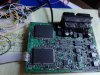
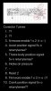
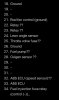
1. take out the ECU
2. Install the flashing program on your computer and register an account (the license for ONE ECU comes with your purchase). There's a driver install as well but it was automatically ran by the initial program for me.
3. Plugin the gear in your USB port and connect the ECU
4. Start the ECu flashing suite program
5. Load the flash map that has been provided by the service of your choice
6. Right click the map and click flash. Follow the instructions.
7. Wait until done (3-4 minutes)
8. unplug and reinstall ECU in your bike. Done! The entire process takes less than an hour.
Very simple and, at least for me, I preferred to pay the 350 bucks for the equipment (I also paid shipping and import fees which were about the same price as the gear itself) rather than send my ECU out for months.
With the gear, you can also flash your friends' bikes as long as they pay for the additional license. There are some caveats there that surpass the scope of this howto.
Hope this helps some that are on the fence!
I wanted to post this briefly, as I think many are on the fence about flashing their bikes due to waiting times. Especially those of you, as I, who are not living near the flashing shops and would have to wait weeks if not months to get your ECU chip back.
Well, I read a lot about flashing services, and I really liked what was being said about 2wheeldynoworks. I contacted them and said that although I am no bike expert, I am quite techy and I wonder if I can do this myself. I quickly received a response that, yes, indeed, I would just have to purchase the flashing gear (about 380 bucks) and the custom flash map that they sell (about 250 bucks), and they'd send it down here. I could reflash my bike as many times as I wanted, and any updates to their mapping would be free for the future. So I did that.
Here are the links for the flashing gear:
* https://2wheeldynoworks.com/products/12-13-yamaha-xt1200-super-tenere-data-link-ecu-flashing-kits (my bike is 2012. Make sure you choose the right gear for your bike's year)
* https://2wheeldynoworks.com/products/2wdw-custom-ftecu-mapping
They will ask you for your ECU PART NUMBER AND ECU SERIAL NUMBER. You won't receive the flash maps until you provide this.
For brevity, if anyone's interested, here's what sparked my interest in this company's specific flashing service (copy paste from another member's statement on here):
- Disable ais - no more decel popping (valve always closed via ecu disable)
- Smode: 1:1 linear throttle with no power restrictions in any gears
- Tmode: sub 1:1 throttle below 50% throttle with smoothing down low. Above 50% throttle and T mode becomes S mode (identical fueling)
– Disable Injector Decel Cut
– Professional fuel map modification for my aftermarket exhaust
– Removal of all gear based or speed dependent restrictions, TRE
– Optimized timing maps for 91+ octane
– Reduce Fan Temps 205°F
– Bypass EXUP Valve (if the tenere has it, cant remember)"
In my case, I asked for mapping specific for shitty fuel as the octane here (in Colombia) is low. I also have an arrow header and two brothers can, so they specified that for me. I also wanted to keep my engine breaking in touring mode.
The flashing process was very simple and took 3-4 minutes.
1. take out the ECU
2. Install the flashing program on your computer and register an account (the license for ONE ECU comes with your purchase). There's a driver install as well but it was automatically ran by the initial program for me.
3. Plugin the gear in your USB port and connect the ECU
4. Start the ECu flashing suite program
5. Load the flash map that has been provided by the service of your choice
6. Right click the map and click flash. Follow the instructions.
7. Wait until done (3-4 minutes)
8. unplug and reinstall ECU in your bike. Done! The entire process takes less than an hour.
Very simple and, at least for me, I preferred to pay the 350 bucks for the equipment (I also paid shipping and import fees which were about the same price as the gear itself) rather than send my ECU out for months.
With the gear, you can also flash your friends' bikes as long as they pay for the additional license. There are some caveats there that surpass the scope of this howto.
Hope this helps some that are on the fence!