For you Gen 2 Super Tenere Owners contemplating the installation of the STS System (https://safer-turn.com) but are reluctant because it requires cutting OEM wires, here is a way to avoid cutting the OEM wire loom. Make your own substitute wire harness.
Instructions for the STS, call for cutting the left, right and ground OEM wires running from the handlebar turn signal switch to the connection with the main or sub frame wire harness of the Super Tenere. If the STS is eventually removed, the cut wires can be connected back together with the remaining STS butt connectors. However, the cut wires still remain. A way to avoid cutting the OEM bike wires is to build a wire harness with male and female connectors that will mate with the existing bike connectors and cut the wires on the substitute harness in lieu of cutting the OEM wires. If the STS is removed, simply reconnect the exiting OEM male and female connectors. Thus, a plug and play solution.
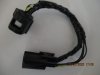
I have not received my STS yet, but I have made a plug and play type harness in preparation of the install. My Super Tenere (2019 ES model) uses a male and female 10 pin Sumitomo TS025 connector wire loom located under the right side access panel housed in a large plastic sheath. Rather than cut the OEM wires that run between the male and female 10 pin connectors, I made a substitute harness.
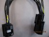
Through research, I discovered that late model Toyota and Lexus autos use the same 10 pin Sumitomo connectors in their cruise control and safe distance modules. . I found the ten pin Sumitomo male and female connectors that match up with the OEM connectors on line at Bmotorsports.com. Part numbers CONN-85925 (female) and CONN-86145 (male). The connectors were about $15 a piece, plus shipping when I bought them. You might be able to acquire these from a Toyota or Lexus dealer but my research indicates they would be more expensive through that route. The connectors come with 8 inches of black pigtail wire. I cut the pig tails down to three inches of wire on each on the male and female connector so that my new harness wires were 6 inches long. The new harness could be a little shorter but 6 inches provides more access to the cut wires, more room to work with the STS butt connectors and easier to stow away the substitute harness.
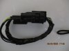
Before actually soldering the wires for a permanent substitute harness, I carefully matched the pins and wires on the purchased male and female connectors and put together the wires using Pinlock connectors. I plugged this temporary harness into the bike connectors to test the substitute harness to make sure all the functions controlled by the handlebar switch functioned as designed like the turn signals, the headlights, the cruise control switch and horn. After the successful test, I soldered all the connections and covered with heat shrink for weather protection.
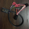
From there, it is a matter of locating the three respective wires from the turn signal switch which are now on the substitute harness and making the installation without cutting the OEM wires. You can locate the appropriate three wires by checking continuity of the OEM wires with the turn signals switched on. The three respective wires on the substitute harness can be cut and follow the STS instructions the same as if you had cut the OEM wires. If you remove the STS system, you simply unplug the substitute harness and reconnect the existing male and female connectors.
Instructions for the STS, call for cutting the left, right and ground OEM wires running from the handlebar turn signal switch to the connection with the main or sub frame wire harness of the Super Tenere. If the STS is eventually removed, the cut wires can be connected back together with the remaining STS butt connectors. However, the cut wires still remain. A way to avoid cutting the OEM bike wires is to build a wire harness with male and female connectors that will mate with the existing bike connectors and cut the wires on the substitute harness in lieu of cutting the OEM wires. If the STS is removed, simply reconnect the exiting OEM male and female connectors. Thus, a plug and play solution.
I have not received my STS yet, but I have made a plug and play type harness in preparation of the install. My Super Tenere (2019 ES model) uses a male and female 10 pin Sumitomo TS025 connector wire loom located under the right side access panel housed in a large plastic sheath. Rather than cut the OEM wires that run between the male and female 10 pin connectors, I made a substitute harness.
Through research, I discovered that late model Toyota and Lexus autos use the same 10 pin Sumitomo connectors in their cruise control and safe distance modules. . I found the ten pin Sumitomo male and female connectors that match up with the OEM connectors on line at Bmotorsports.com. Part numbers CONN-85925 (female) and CONN-86145 (male). The connectors were about $15 a piece, plus shipping when I bought them. You might be able to acquire these from a Toyota or Lexus dealer but my research indicates they would be more expensive through that route. The connectors come with 8 inches of black pigtail wire. I cut the pig tails down to three inches of wire on each on the male and female connector so that my new harness wires were 6 inches long. The new harness could be a little shorter but 6 inches provides more access to the cut wires, more room to work with the STS butt connectors and easier to stow away the substitute harness.
Before actually soldering the wires for a permanent substitute harness, I carefully matched the pins and wires on the purchased male and female connectors and put together the wires using Pinlock connectors. I plugged this temporary harness into the bike connectors to test the substitute harness to make sure all the functions controlled by the handlebar switch functioned as designed like the turn signals, the headlights, the cruise control switch and horn. After the successful test, I soldered all the connections and covered with heat shrink for weather protection.
From there, it is a matter of locating the three respective wires from the turn signal switch which are now on the substitute harness and making the installation without cutting the OEM wires. You can locate the appropriate three wires by checking continuity of the OEM wires with the turn signals switched on. The three respective wires on the substitute harness can be cut and follow the STS instructions the same as if you had cut the OEM wires. If you remove the STS system, you simply unplug the substitute harness and reconnect the existing male and female connectors.